
Installing Self-Clinching Standoffs (CFSO / CFBSO Series Installation Guide)
Three-step installation procedure for the self-clinching standoff series — punch or drill the correct-size mounting hole without deburring, enter the pilot end from the punched side, then press with parallel punch and anvil under steady squeezing force until the flange contacts the sheet. Qualitative manufacturer procedure covering CFSO, CFSOS, CFSOA, CFBSO, CFBSOS and CFBSOA.
Last updated: 2026-11
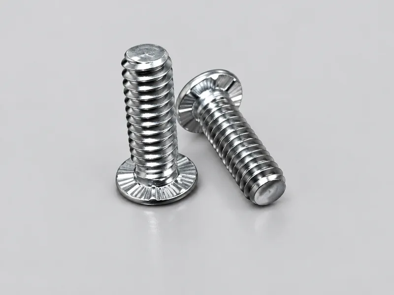
Specifications
This page collects the manufacturer's installation procedure for the self-clinching standoff series — the through-threaded CFSO, CFSOS and CFSOA and the blind CFBSO, CFBSOS and CFBSOA all install by the same three steps. It is a qualitative guide: the collected installation sheet specifies the sequence and the tooling conditions but no per-size numbers, so the mounting-hole dimensions, minimum sheet thickness and performance figures for a specific part live on that part's series page rather than here. The procedure is short on purpose — clinching needs no reaming, threading, welding or adhesives, and the whole installation is one squeeze of a press. For per-size mounting geometry and performance tables, use the CFSO/CFSOS/CFSOA through-threaded page, the CFBSO/CFBSOS/CFBSOA blind pages, or the BSO/BSOS/BSOA metric family page.
| Applies to | CFSO, CFSOS, CFSOA (through-threaded) and CFBSO, CFBSOS, CFBSOA (blind) self-clinching standoffs — the installation sheet covers all six series with one procedure |
|---|---|
| Step 1 — mounting hole | Punch or drill the mounting hole to the correct size in the sheet material. Do not deburr and do not perform any secondary operations on the hole — the procedure states this explicitly |
| Step 2 — placement | Place the pilot end of the standoff into the mounting hole, preferably entering from the punched side of the sheet |
| Step 3 — pressing | With the punch and anvil surfaces parallel, apply a steady squeezing force until the flange contacts the mounting sheet |
| Tooling | A squeeze-type press arrangement with a punch on one side and an anvil on the other; the manufacturer's installation diagram depicts the suggested tooling for applying these forces |
| What this guide does not include | Per-size mounting-hole dimensions, tolerances, minimum sheet thickness, and installation/performance figures — those render on the individual series pages; the installation sheet itself is qualitative in its text layer |
| MOQ / lead time | Not owner-confirmed for this family — confirmed at quotation |
Materials
- Procedure applies regardless of standoff material — carbon steel (CFBSO), stainless (CFSOS, CFBSOS), aluminum (CFSOA, CFBSOA), through-threaded or blind
Ordering & documentation
Documents
Shipments are backed by Mill Test Certificate (MTC), Dimensional Report, Salt Spray Test Report on request, with full batch traceability from raw material to finished product. Quality management follows the owner-confirmed compliance list: ISO 9001:2015, RoHS, REACH. Exact document sets are confirmed on the order.
Quotation
- The fastener family (Installing Self-Clinching Standoffs (CFSO / CFBSO Series Installation Guide)) plus the standard designation from your drawing — DIN / ISO / JIS / ASTM / ANSI, or a drawing for custom parts.
- Size (diameter and length), thread type (metric or inch), property class or grade, and coating or finish.
- Quantity per size and your target delivery date.
- Destination country, and any required documents (for example a mill test certificate) so the quote includes them.
Sample & supply
Minimum order quantities and lead times for this family are confirmed at quotation — send your sizes, grades and quantities on the RFQ and the quote will carry a firm schedule. Sample availability is confirmed with the quotation.
Storage & shipping
Parts are packed for export and shipped factory-direct to buyers in Europe, Asia, the Americas and the Middle East. Store fasteners dry and protected until installation, and keep coated parts in their packaging until use; specific packing and preservation requirements can be stated on the order and confirmed at quotation.
Frequently asked questions
Why can't I deburr or chamfer the mounting hole before installation?
The installation procedure is explicit: punch or drill the correct-size hole and do not deburr or perform any secondary operations. This is a stated condition of the procedure, not a suggestion — clinching seats the standoff by pressing it into the hole as prepared, and the sheet's own series pages describe the panel material cold-flowing into the clinching feature during that press. The procedure does not describe a deburred or reworked hole as an acceptable variant, so the safe reading is to follow the sequence as printed: correct-size hole, no secondary operations, pilot end in, parallel squeeze.
What tooling does installation require?
Two surfaces that stay parallel — a punch on one side of the sheet and an anvil on the other — squeezed together with a steady force until the standoff's flange contacts the sheet. The manufacturer's installation diagram depicts the suggested punch-and-anvil arrangement; the collected sheet specifies the parallelism and the steady-squeeze condition rather than a press model or a force value. Installation-force figures at specific sheet thicknesses are published per series on the CFSO and CFBSO series pages from the collected catalog, so a press sized for your part can be checked there.
Is the procedure different for the blind CFBSO series?
No — the installation sheet lists all six series (CFSO, CFSOS, CFSOA through-threaded; CFBSO, CFBSOS, CFBSOA blind) under one installation procedure: same hole preparation without deburring, same pilot-end-first placement from the punched side, same parallel punch-and-anvil squeeze until flange contact. What differs between the series is not the installation but the part: the blind standoffs close the far end to control screw penetration, come in different panel-hardness ceilings per material, and have their own geometry and performance tables — see the CFBSO, CFBSOS and CFBSOA pages.
What should accompany an RFQ so the right standoff ships installable?
State the series (through-threaded CFSO/CFSOS/CFSOA or blind CFBSO/CFBSOS/CFBSOA — or the metric BSO/BSOS/BSOA ladder), thread size, body size, nominal length, sheet material, thickness and hardness, and quantity per size, plus destination country. If your shop installs with a specific press, mention the sheet thickness so installation force can be checked against the tabulated rows. Commercial terms are confirmed at quotation.
Request a Quote
Get factory-direct pricing from the manufacturer.
What to include in your inquiry
- ✓ Standard and property class (e.g. DIN 912, ISO 4762, class 8.8) — or a drawing for custom parts.
- ✓ Sizes, lengths and thread type (metric or inch).
- ✓ Quantity per size and your target delivery date.
- ✓ Destination country, plus any coating or finish requirement.
- ✓ Any documents you need with the shipment (e.g. mill test certificate) so the quote includes them.
- ✓ Your inquiry goes straight to the factory team by email and gets a reply within 24 hours.
- ✓ Factory-direct pricing
- ✓ Standard and custom specifications
- ✓ Factory-direct export to buyers in Europe, Asia, the Americas and the Middle East
- ✓ Full fastener family support