
DIN 7965 Slotted Inserts (M3 – M20)
DIN 7965 slotted inserts, M3 to M20 — groove-driven threaded inserts with a 6H internal thread, collected per-size table (external diameter, hole diameter, groove width and depth, internal-thread length) plus the source's offered length/size matrix, steel or brass.
Last updated: 2026-11
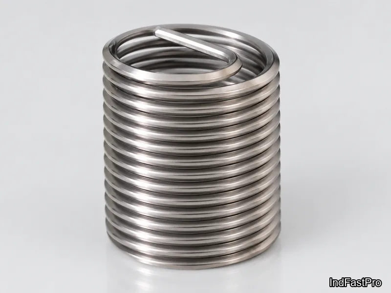
Specifications
DIN 7965, as the collected source prints it, is a slotted insert: a threaded insert whose outside wall carries drive grooves and whose inside carries a ready-cut 6H internal thread. You tap the parent material, turn the insert in over the hole diameter d4, and the groove width n and depth t on its face take the driving tool; the legend speaks the part's own language — d2 is the "external diameter of the nut", l2 the "length of the internal thread", and the thread column is 6H, an internal nut thread, which is what separates this part from any screw that shares a DIN number with it. The collected table runs M3 through M20 and prints, per size, the outside diameters d2/d3/d5, the hole diameter d4 you drill or tap up to, the groove pair n/t, the height h and the internal-thread length l2 — with d5, h and z printed by the source without legend definitions and carried here under their own letters exactly as printed. The offered length/size combinations sit in the source's own matrix under l1: one length per size across most of the ladder (M3 at 8, M4 at 10, up to M20 at 30), and three matrix rows — 20, 40 and 50 — that the source leaves entirely unplaced; those gaps are the source's own, not missing data, and other combinations are quoted to drawing. Steel and brass come from the source's Makings panel; stainless and plastic print "-" there, so they are not claimed, and finishes are per RFQ.
| Standard / scope | DIN 7965 slotted inserts, M3 to M20 (internal thread d1 is the size ladder itself: M3, M4, M5, M6, M8, M10, M12, M16, M20) |
|---|---|
| Outside diameters | d2 6 → 29; d3 (thread run) 4,5 → 24; d5 5 → 26 across the ladder — d5/h/z print without a legend definition in the source and are carried under their own letters |
| Hole diameter | d4 3,5 → 21 — the parent-material hole the insert installs over, per size |
| Groove drive | n (groove width) 1 → 5 paired with t (groove depth) 2 → 6 per size — the slotted drive face |
| Height / internal thread | h 2 → 5; l2 (length of the internal thread) 5 → 20, flat at 16 for M12 and M16 as printed |
| Offered lengths | Source l1 matrix: one placed length per size across M3-M20 (8/10/12/15/18/25/30 by size; M12/M16/M20 share 30); rows 20, 40 and 50 unplaced by the source — other combinations quoted to drawing |
| Materials / thread | Steel; brass (source "Non Ferrous"); thread 6H internal (source panel). Stainless and plastic print "-" in the source — not claimed; finishes per RFQ |
| d1 | M3 | M4 | M5 | M6 | M8 | M10 | M12 | M16 | M20 |
|---|---|---|---|---|---|---|---|---|---|
| d2 | 6 | 8 | 10 | 12 | 16 | 18,5 | 22 | 25 | 29 |
| d3 | 4,5 | 5,5 | 7,5 | 9,5 | 12,5 | 15 | 18 | 20,5 | 24 |
| d4 | 3,5 | 4,5 | 6 | 7,5 | 10 | 12 | 15 | 17,5 | 21 |
| d5 | 5 | 6,5 | 8,5 | 10,5 | 14,5 | 17 | 20 | 22,5 | 26 |
| h | 2 | 2,5 | 3,5 | 4 | 5 | 5 | 5 | 5 | 5 |
| l2 | 5 | 6 | 7 | 9 | 11 | 13 | 16 | 16 | 20 |
| n | 1 | 1,2 | 1,6 | 2 | 2,5 | 3 | 3 | 4 | 5 |
| t | 2 | 2 | 3 | 3 | 4 | 5 | 5 | 6 | 6 |
| z | 0,6 | 0,6 | 0,8 | 1 | 1 | 1,6 | 1,6 | 1,6 | 1,6 |
- Rows d5, h and z are not defined in the source's legend (which lists l, d, d2, d4, n, t, d3, l2 only); transcribed verbatim under the table's own letters.
- Legend names the nominal thread "d" while the table header prints "d1" — letter mismatch carried as printed.
- l2 is non-monotonic as printed (16 at M12 and 16 at M16 — flat, not falling); verbatim, noted for quoting engineers.
| l1 | M3 | M4 | M5 | M6 | M8 | M10 | M12 | M16 | M20 |
|---|---|---|---|---|---|---|---|---|---|
| 8 | x | ||||||||
| 10 | x | ||||||||
| 12 | x | ||||||||
| 15 | x | ||||||||
| 18 | x | ||||||||
| 20 | |||||||||
| 25 | x | ||||||||
| 30 | x | x | x | ||||||
| 40 | |||||||||
| 50 |
- Rows 20, 40 and 50 carry no "x" in any size column — the source places no size for those lengths; kept verbatim, never interpolated. Other combinations are quoted to drawing.
- The matrix label row (l1) prints as a row of empty cells in the live grid (crushed rowspan sub-header); the block is rendered here with l1 as the row-label column header.
Materials
- Steel and brass, per the collected source's Makings panel (brass under "Non Ferrous" — the softer parent-material option); the source lists stainless and plastic as "-", so neither is claimed; finish confirmed at quotation (tenant supply range)
Ordering & documentation
Documents
Shipments of DIN 7965 Slotted Inserts (M3 – M20) are backed by Mill Test Certificate (MTC), Dimensional Report, Salt Spray Test Report on request, with full batch traceability from raw material to finished product. Quality management for DIN 7965 Slotted Inserts (M3 – M20) orders follows the owner-confirmed compliance list: ISO 9001:2015, RoHS, REACH. Exact document sets are confirmed on the order.
Quotation
- The product family (DIN 7965 Slotted Inserts (M3 – M20)), product standard/designation and drawing or part number.
- The dimensions that apply to this part — such as size, pitch, length, thickness, fit, grip or groove geometry.
- Material/grade, heat-treatment condition and surface finish, together with the service environment.
- Quantity per size, delivery destination and required test or traceability documents.
Sample & supply
Minimum order quantities and lead times for din 7965 slotted inserts (m3 – m20) are confirmed at quotation — send insert type, thread size and installation method on the RFQ and the quote will carry a firm schedule; sample availability is confirmed with the quotation.
Storage & shipping
DIN 7965 Slotted Inserts (M3 – M20) are packed for export and shipped factory-direct to buyers in Europe, Asia, the Americas and the Middle East. Store din 7965 slotted inserts (m3 – m20) dry and protected until installation, and keep coated parts in their packaging until use; specific packing and preservation requirements can be stated on the order and confirmed at quotation.
Frequently asked questions
What does DIN 7965 install into, and which number do I machine to?
The hole. The table's d4 column is the source's own "hole diameter" — the bore in the parent material the insert seats over — and it sits under the outside diameters d2/d3/d5 at every size. Machine the parent to d4, tap it to the matching internal size, then drive the insert home on its slot face: n (groove width) and t (groove depth) are the two numbers the driving tool sees, and h is the installed height above the surface. The internal-thread length l2 tells you how much engaged thread the insert actually delivers — at M20 that is 20 mm of 6H thread from a 30 mm-long insert. Take d4 straight from the row for your size; the source does not tabulate parent-material corrections, so soft-parent compensation stays a drawing or RFQ decision.
What does an RFQ for DIN 7965 need to state?
Internal thread size (d1, M3-M20) and length — the collected matrix lists one placed length per size (M3 at 8 up to M20 at 30, with M12/M16/M20 all placed at 30); rows 20, 40 and 50 print no placed size in the source, so other combinations are quoted to drawing. State the material (steel or brass from the collected panel), the parent material the insert goes into, quantity, and any certificate requirement such as an EN 10204 3.1 mill report. If the drawing dimensions the bore or counterbore, send it — d4 is what the hole sees, and the table on this page gives it per size alongside the groove pair n/t the installer needs.
The legend says "nut" and the thread is 6H — why is this page under threaded inserts?
Because that vocabulary is the point. The collected source titles DIN 7965 "Slotted inserts" and defines its own letters as nut/insert geometry: d2 "external diameter of the nut", d4 "hole diameter", n and t as groove width and depth, l2 "length of the internal thread", and a 6H column — an internal thread class, which no external screw thread carries. The same page's own listing rows read "GROOVED INSERT M3 DIN 7965" and "DIN 7965 slotted inserts". This page reproduces the source's identity and legend verbatim rather than adjudicating the DIN number against other catalogs' usages; if your drawing calls a DIN 7965 part whose geometry contradicts the table above, state the part type and the geometry you need on the RFQ so the quotation is made against the drawing, not against the number.
Request a Quote
Get factory-direct pricing from the manufacturer.
What to include in your DIN 7965 Slotted Inserts (M3 – M20) inquiry
- ✓ Identify insert type (helical/tangless, solid, self-tapping, key-locking, heat-set or rivet nut) and internal thread.
- ✓ Give insert length, parent-material type/hardness, available wall thickness and hole dimensions.
- ✓ State installation method and tooling, including tapping or prepared-hole requirements.
- ✓ Describe required pull-out/torque-out resistance, anti-rotation or locking needs and service environment.
- ✓ Factory-direct pricing for your DIN 7965 Slotted Inserts (M3 – M20)
- ✓ Standard and custom specifications
- ✓ Factory-direct export to buyers in Europe, Asia, the Americas and the Middle East
- ✓ Full fastener family support