
DIN 7331 Compression Rivets
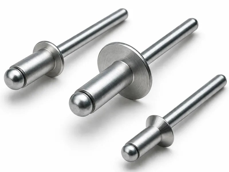
DIN 7331 compression rivets, d1 2 to 6: rivet and die-side geometry (d2, d3, d4, k, l2), plus the hole diameter and clamping length reference table.
Last updated: 2026-11
Specifications
DIN 7331 is the compression (tubular) rivet for fast, low-force setting in press or pincer tooling — the short, stout rivet whose hollow end curls under the die to clamp sheet stacks. The collected 03/2009-edition geometry table is organized by diameter with the source printing d1 columns in repeated pairs (2; 3; 3; 4; 4; 4; 4; 4; 5; 5; 6 — carried verbatim, one column per setting-length variant) and rows for head d2 nom, cavity/shank d3 nom, die-side d4 nom, head height k ≈ and cavity depth l2 ≈. The second table is the working reference the joint designer uses: hole diameter d3 and clamping length l1 (5 to 22 across the range) with the die-side d5 — the values that turn the rivet into a specified joint. Document-fastening, hinge and small-bracket work at production rate is the duty.
| Standard / scope | DIN 7331 compression rivets — d1 2 to 6, edition 03/2009 |
|---|---|
| Rivet geometry | d2 nom (head), d3 nom, d4 nom (die side), k ≈, l2 ≈ per size — repeated d1 columns per setting variant, verbatim as printed |
| Joint reference | Hole diameter d3 and clamping length l1 5 to 22, with die-side d5 — the specification rows for the joint, not just the rivet |
| Not tabulated | Material/temper, setting force, mass — per RFQ |
Materials
- Compression rivets order in mild and case-hardening steel, brass and aluminium — set cold in pincers or press dies, so temper follows the die force available. Give the clamping length (total stack) and hole size from the reference table when ordering for an existing jig; for new joints we size the rivet from the stack against the l1 column and confirm die dimensions d4/d5 on the quotation
Ordering & documentation
Documents
Shipments are backed by Mill Test Certificate (MTC), Dimensional Report, Salt Spray Test Report on request, with full batch traceability from raw material to finished product. Quality management follows the owner-confirmed compliance list: ISO 9001:2015, RoHS, REACH. Exact document sets are confirmed on the order.
Quotation
- The fastener family (DIN 7331 Compression Rivets) plus the standard designation from your drawing — DIN / ISO / JIS / ASTM / ANSI, or a drawing for custom parts.
- Size (diameter and length), thread type (metric or inch), property class or grade, and coating or finish.
- Quantity per size and your target delivery date.
- Destination country, and any required documents (for example a mill test certificate) so the quote includes them.
Sample & supply
Minimum order quantity is 10,000–50,000 pieces depending on size. Standard production run 10–20 days. Quantities or variants outside the standard range are confirmed at quotation.
Storage & shipping
Parts are packed for export and shipped factory-direct to buyers in Europe, Asia, the Americas and the Middle East. Store fasteners dry and protected until installation, and keep coated parts in their packaging until use; specific packing and preservation requirements can be stated on the order and confirmed at quotation.
Frequently asked questions
Why does the geometry table repeat the d1 values across its columns?
Because the source table gives one column per setting-length variant at the same diameter — the repeated 2; 3; 3; 4; 4… print is how the page lists the rivet variants side by side, and the transcription carries it verbatim rather than merging columns. Read each column as a complete rivet: its own d2/d3/d4/k/l2 values, i.e. the geometry of a specific setting configuration. The companion reference table (hole d3, clamping length l1, die d5) is then the selection tool: find your stack length in the l1 row and read across to the rivet column that serves it. If this looks unfamiliar, it is the standard's own layout — send us the stack and tooling and we return the exact column.
What does the clamping length (l1) column actually fix?
The joint: l1 is the total material thickness the rivet is designed to clamp through its setting range — beyond it the cavity cannot close properly and the joint loosens, far short of it and the die bottoms before the clamp develops. That is why the reference table pairs it with the hole diameter d3 and the die-side d5: together they are the complete setting specification — prepared hole, stack limit, die face. Production jigs are built to these three numbers, which is the practical reason to order "DIN 7331 per the table" with the stack stated rather than by rivet number alone: the same rivet serves several stacks across the printed variants, and the correct one is the column whose l1 covers your measured stack.
Request a Quote
Get factory-direct pricing from the manufacturer.
What to include in your inquiry
- ✓ Standard and property class (e.g. DIN 912, ISO 4762, class 8.8) — or a drawing for custom parts.
- ✓ Sizes, lengths and thread type (metric or inch).
- ✓ Quantity per size and your target delivery date.
- ✓ Destination country, plus any coating or finish requirement.
- ✓ Any documents you need with the shipment (e.g. mill test certificate) so the quote includes them.
- ✓ Your inquiry goes straight to the factory team by email and gets a reply within 24 hours.
- ✓ Factory-direct pricing
- ✓ Standard and custom specifications
- ✓ Factory-direct export to buyers in Europe, Asia, the Americas and the Middle East
- ✓ Full fastener family support