
DIN 7338 Rivets for Brake and Clutch Linings
DIN 7338 rivets for brake and clutch linings, shank d1 3–10 mm — the countersunk-head solid rivet with a reduced shoulder shank that seats the friction lining in the shoe, with the collected head/shoulder/shank ladder and the matching fitting data (clearance hole, countersink, projection).
Last updated: 2026-11
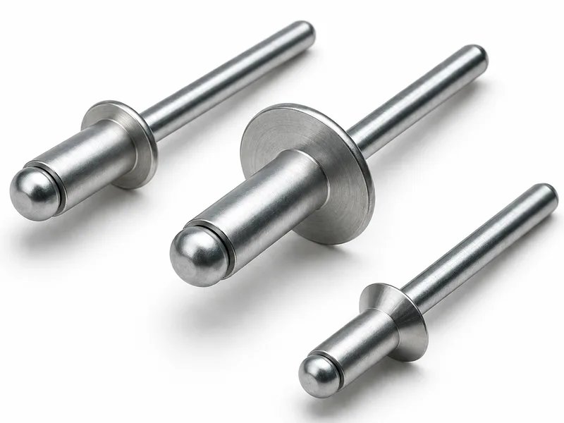
Specifications
Brake and clutch linings are riveted, not bolted: a DIN 7338 rivet is a countersunk-head solid rivet whose shank is turned down below the nominal at the shoulder (d3 min., 2,85 mm at the 3 mm rivet rising to 9,75 mm at the 10 mm rivet) so the lining sits flat against the shoe while the rivet head pulls it down. The collected table runs shank d1 = 3 to 10 mm (h13) and carries per size the countersink base diameter d2 (h14/h15, 5,5 → 18 mm), the clearance-hole and countersink diameters the shoe needs (d4, and the fitting table d7 H12 / d9 H14), the shank under tolerance d10, the head geometry (height e, thickness k, fillet r), and the projection z1 after setting — given as two ladders because a longer rivet (l 22–40) projects differently than a short one (l 5–20). Reading order at the bench: drill the lining to d7 and countersink to d9 off the fitting table for the rivet size, set the rivet so the head sits under the lining countersink, and check the projection z1 matches the ladder for the length used — under-projection means a cold joint, over-projection means the set head stands proud and scores the drum. Materials (the lining rivet is typically a soft brass/aluminium or steel by application) and length ladders are not tabulated by the collected specification — per RFQ.
| Standard | DIN 7338 — rivets for brake linings and clutch linings (countersunk head, shouldered shank) |
|---|---|
| Size range | Shank d1 3 – 10 mm (h13), six sizes in the collected ladder (3, 4, 5, 6, 8, 10) |
| Head / countersink | d2: 5,5 → 18 mm (h14 at d1 3–5, h15 at 6–10 per the source tolerance split); head height e (max) 1,5 → 5 mm; thickness k 0,8 → 1,4 mm |
| Shoulder / shank | d3 (min.) 2,85 → 9,75 mm; hole d4 (H13) 1,7 → 7,5 mm; shank under tolerance d10 1,66 → 7,18 mm |
| Fitting data | Clearance hole d7 (H12) 3,1 → 10,5 mm; countersink d9 (H14) 6,5 → 19 mm; projection z1: 2,5–6 mm (l 5–20) / 6–7 mm (l 22–40) |
| Materials / length ladder | Not tabulated by the collected specification — per RFQ (state lining material, shoe thickness and environment at quotation) |
| Shank Dia. (d1 h13) | Head Dia. (d2) | Shoulder Dia. (d3 min.) | Hole Dia. (d4 H13) | Shank Under Tol. (d10) | Head Height (e max.) | Head Thick. (k) | Fillet (r max.) | s | s´ min. | Shoulder Length (t) |
|---|---|---|---|---|---|---|---|---|---|---|
| 3 | 5,5 | 2,85 | 1,7 | 1,66 | 1,5 | 0,8 | 0,2 | 0,5 | 0,4 | 3,5 |
| 4 | 7,5 | 3,8 | 2,7 | 2,62 | 2 | 1 | 0,3 | 0,5 | 0,4 | 4 |
| 5 | 9,5 | 4,8 | 3,5 | 3,42 | 2,5 | 1 | 0,3 | 0,6 | 0,5 | 4 |
| 6 | 11,5 | 5,8 | 4,2 | 4,12 | 3 | 1,2 | 0,4 | 0,75 | 0,6 | 6 |
| 8 | 15,5 | 7,75 | 6 | 5,18 | 4 | 1,2 | 0,4 | 1,2 | 1 | 8 |
| 10 | 18 | 9,75 | 7,5 | 7,18 | 5 | 1,4 | 0,6 | 1,2 | 1 | 10 |
- Row 1 (3): The source splits the d2 tolerance across two cells ("tolerance | h14 | h15") for the 3–5 mm and 6–10 mm ranges; the table above carries the nominal d2 values with the tolerance note here. A stray length ladder row ("4 5 6 8 10 12") appears at the table tail with empty cells — treated as the source length list, not data, and not reproduced as a data row.
| Shank Dia. (d1) | Clearance Hole (d7 H12) | Countersink Dia. (d9 H14) | Projection z1 (l = 5–20) | Projection z1 (l = 22–40) |
|---|---|---|---|---|
| 3 | 3,1 | 6,5 | 2,5 | - |
| 4 | 4,2 | 8,5 | 3 | - |
| 5 | 5,2 | 10,5 | 4,5 | - |
| 6 | 6,3 | 12,5 | 5 | 6 |
| 8 | 8,4 | 16,5 | 5 | 6 |
| 10 | 10,5 | 19 | 6 | 7 |
Materials
- Material specified per RFQ — brake/clutch rivets see heat and shear every cycle; state the application (drum, disc, clutch plate), the lining and the shoe material with the order
Ordering & documentation
Documents
Shipments are backed by Mill Test Certificate (MTC), Dimensional Report, Salt Spray Test Report on request, with full batch traceability from raw material to finished product. Quality management follows the owner-confirmed compliance list: ISO 9001:2015, RoHS, REACH. Exact document sets are confirmed on the order.
Quotation
- The fastener family (DIN 7338 Rivets for Brake and Clutch Linings) plus the standard designation from your drawing — DIN / ISO / JIS / ASTM / ANSI, or a drawing for custom parts.
- Size (diameter and length), thread type (metric or inch), property class or grade, and coating or finish.
- Quantity per size and your target delivery date.
- Destination country, and any required documents (for example a mill test certificate) so the quote includes them.
Sample & supply
Minimum order quantity is 10,000–50,000 pieces depending on size. Standard production run 10–20 days. Quantities or variants outside the standard range are confirmed at quotation.
Storage & shipping
Parts are packed for export and shipped factory-direct to buyers in Europe, Asia, the Americas and the Middle East. Store fasteners dry and protected until installation, and keep coated parts in their packaging until use; specific packing and preservation requirements can be stated on the order and confirmed at quotation.
Frequently asked questions
How do I fit DIN 7338 lining rivets — what do I drill, and how do I judge the set?
Two tables off this page do the fitting work. The fitting table is the drill chart: for each rivet size, drill the lining at d7 (H12 — 3,1 mm for the 3 mm rivet up to 10,5 mm for the 10 mm) and countersink at d9 (H14 — 6,5 mm up to 19 mm), which sets how deep the countersunk head buries into the lining. The geometry table is the set check: after setting, the projection z1 tells you whether the joint closed — for short rivets (l 5–20) expect roughly 2,5–6 mm of projected shank to close into the head depending on size, for long rivets (l 22–40) expect 6–7 mm at the 6–10 mm sizes (the smaller sizes are not established for the long ladder — quote them explicitly). Two cautions: the d2 tolerance class splits across the series (h14 at 3–5 mm, h15 at 6–10 mm) and prints a stray length row at the table tail, both flagged under the table. What the table does not carry: rivet material (brass, aluminium and soft steel all appear in the trade by application), full length ladders and per-length stock — all RFQ lines, so state the application and lining stack at quotation.
Request a Quote
Get factory-direct pricing from the manufacturer.
What to include in your inquiry
- ✓ Standard and property class (e.g. DIN 912, ISO 4762, class 8.8) — or a drawing for custom parts.
- ✓ Sizes, lengths and thread type (metric or inch).
- ✓ Quantity per size and your target delivery date.
- ✓ Destination country, plus any coating or finish requirement.
- ✓ Any documents you need with the shipment (e.g. mill test certificate) so the quote includes them.
- ✓ Your inquiry goes straight to the factory team by email and gets a reply within 24 hours.
- ✓ Factory-direct pricing
- ✓ Standard and custom specifications
- ✓ Factory-direct export to buyers in Europe, Asia, the Americas and the Middle East
- ✓ Full fastener family support