
Open-End Blind Rivets (DIN 7337 / ISO 15977)
Open-end blind rivets per DIN 7337 / ISO 15977 — dome, countersunk and large flange heads, aluminum, steel and stainless bodies with steel or stainless mandrels, from 3/32″ to 1/4″ (2.4–6.4 mm). DIN 7337 dimensions, minimum shear/tensile by body material and grip-length tables; the standard one-sided fastener for thin-sheet joints.
Last updated: 2026-11
Specifications
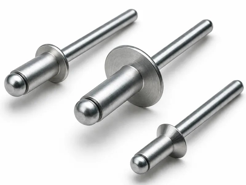
The open-end blind rivet is the default one-sided fastener: a tubular body with a through mandrel, set from one side when the back of the joint cannot be reached. The mandrel is drawn into the body with a rivet gun, expanding the blind end and snapping the mandrel off — a strong, vibration-resistant joint without marring the joined surfaces. The collected trade-size table runs 3/32″ through 1/4″ bodies, each in a ladder of grip lengths from roughly 1/16″ up to 1″; the metric series runs 2.4 to 6.4 mm. Bodies and mandrels combine by application: an aluminum body with a steel mandrel for general sheet work, or all-stainless where the joint must not corrode at either side. The collected DIN 7337 tables carry the dimension and tolerance series (body d1 2.4–6.4 mm, head d2 5–13 mm, head height k 0.55–1.8 mm), the joint hole d3 for every body size, minimum shear and tensile force by body material, and grip-length ladders per body/mandrel combination — see the specification below. Open-end construction leaves the set rivet hollow through the center — where the hole must stay sealed or the joint watertight, step up to a closed-end rivet.
| Standard | DIN 7337 / ISO 15977 — open-end blind rivets (break-mandrel) |
|---|---|
| DIN 7337 dimensions | Body d1 2.4–6.4 mm (tolerances +0.08/−0.1 to +0.08/−0.15); head diameter d2 5–13 mm; head height k 0.55–1.8 mm; r max 0.2–0.5 mm — series limits per the collected DIN 7337 table |
| DIN 7337 joint hole (d3 nom) | d1 2.4 / 3 / 3.2 / 4 / 4.8 / 5 / 6 / 6.4 mm → hole 2.5 / 3.1 / 3.3 / 4.1 / 4.9 / 5.1 / 6.1 / 6.5 mm |
| DIN 7337 minimum shear | At d1 4.8 mm: aluminium 1400 N, steel 2400 N, A2 stainless 3800 N; at 6.4 mm: aluminium 2800 N, steel 3600 N — minimum values per body material |
| DIN 7337 minimum tensile | At d1 4.8 mm: aluminium 1200 N, steel 3000 N, A2 stainless 4500 N; at 6.4 mm: aluminium 2100 N, steel 4000 N — minimum values per body material |
| DIN 7337 grip ranges (aluminium body, sample) | d1 4.8 mm: length 6 → 2–3 mm, 25 → 16–21 mm, 50 → 40–45 mm; d1 6.4 mm: length 12 → 2–6 mm, 25 → 14–18 mm, 50 → 39–44 mm |
| Rivet length tolerance | Rivet length may run 1 mm longer to 0.2 mm shorter (collected DIN 7337 guide) |
| Body diameters (metric) | 2.4, 3.0, 3.2, 4.0, 4.8, 5.0, 6.0, 6.4 mm (series depends on rivet line, material and maker) |
| Trade sizes (inch) | 3/32″, 1/8″, 5/32″, 3/16″, 1/4″ — sampled trade sizes: 32 (3/32″, grip 0.032″–0.125″, length 0.225″); 42 (1/8″, grip 0.063″–0.125″, length 0.250″); 66 (3/16″, grip 0.251″–0.375″, length 0.550″); 816 (1/4″, grip 0.876″–1.000″, length 1.205″/1.245″) |
| Hole & drill size | 3/32″ → #41 drill (0.097″–0.100″); 1/8″ → #30 (0.129″–0.133″); 5/32″ → #20 (0.160″–0.164″); 3/16″ → #11 (0.192″–0.196″); 1/4″ → F (0.257″–0.261″). Metric guidance: hole ≈ 0.1 mm over nominal diameter (e.g. 4.9 mm for 4.8 mm) |
| Grip range | Per trade size — e.g. 1/8″ bodies span 0.032″ to 0.625″ across the length ladder; select so total stack thickness falls inside the published range |
| Length estimate | Body length ≈ total grip thickness + rivet diameter (preliminary estimate; confirm against the selected product data) |
| Head styles | Dome; 120° countersunk (flush); large flange (soft or brittle sheets) |
| Typical strengths (1/8″ stainless, catalog sheet) | Shear 550 lbf; tensile 700 lbf (3/32″ row: 230 / 320 lbf). Values are catalog typicals, not a design allowables table |
| MOQ / lead time | 10,000–50,000 pieces by size; 10–20 days |
| Body Dia. | Work Hole & Drill | Grip Range (G) | Body Length Max (L) | Head Dia. Nom (B) | Head Ht Max (C) | Shear (lbf) | Tensile (lbf) | Part Numbers (POP® / SSD / Avdel®) |
|---|---|---|---|---|---|---|---|---|
| .094 (3/32) | .097/.100 — #41 | .031-.125 | .250 | .180 | .032 | 230 | 320 | PTSD302 / — / CSPS-03-02 |
| .125 (1/8) | .129/.133 — #30 | .031-.062 | .203 | .250 | .040 | 550 | 700 | PTSD401 / SSD41BS / CSPS-04-01 |
| .125 (1/8) | .129/.133 — #30 | .063-.125 | .265 | .250 | .040 | 550 | 700 | PTSD402 / SSD42BS / CSPS-04-02 |
| .125 (1/8) | .129/.133 — #30 | .126-.187 | .328 | .250 | .040 | 550 | 700 | PTSD403 / SSD43BS / CSPS-04-03 |
| .125 (1/8) | .129/.133 — #30 | .188-.250 | .390 | .250 | .040 | 550 | 700 | PTSD404 / SSD44BS / CSPS-04-04 |
| .125 (1/8) | .129/.133 — #30 | .251-.312 | .453 | .250 | .040 | 550 | 700 | PTSD405 / SSD45BS / CSPS-04-05 |
| .125 (1/8) | .129/.133 — #30 | .313-.375 | .515 | .250 | .040 | 550 | 700 | PTSD406 / SSD46BS / CSPS-04-06 |
| .125 (1/8) | .129/.133 — #30 | .376-.500 | .640 | .250 | .040 | 550 | 700 | PTSD408 / SSD48BS / CSPS-04-08 |
| .156 (5/32) | .160/.164 — #20 | .063-.125 | .290 | .312 | .047 | 900 | 1130 | PTSD502 / SSD52BS / CSPS-05-02 |
| .156 (5/32) | .160/.164 — #20 | .126-.250 | .415 | .312 | .047 | 900 | 1130 | PTSD504 / SSD54BS / CSPS-05-04 |
| .156 (5/32) | .160/.164 — #20 | .251-.375 | .540 | .312 | .047 | 900 | 1130 | PTSD506 / SSD56BS / CSPS-05-06 |
| .187 (3/16) | .192/.196 — #11 | .063-.125 | .315 | .375 | .055 | 1000 | 1375 | PTSD602 / SSD62BS / CSPS-06-02 |
| .187 (3/16) | .192/.196 — #11 | .126-.250 | .440 | .375 | .055 | 1000 | 1375 | PTSD604 / SSD64BS / CSPS-06-04 |
| .187 (3/16) | .192/.196 — #11 | .251-.375 | .565 | .375 | .055 | 1000 | 1375 | PTSD606 / SSD66BS / CSPS-06-06 |
| .187 (3/16) | .192/.196 — #11 | .376-.500 | .690 | .375 | .055 | 1000 | 1375 | PTSD608 / SSD68BS / CSPS-06-08 |
| .187 (3/16) | .192/.196 — #11 | .501-.625 | .815 | .375 | .055 | 1000 | 1375 | PTSD610 / SSD610BS / CSPS-06-10 |
| .250 (1/4) | .257/.261 — F | .020-.250 | .500 | .500 | .069 | 1400 | 1920 | PTSD804 / — / CSPS-08-04 |
| .250 (1/4) | .257/.261 — F | .500-.625 | .865 | .500 | .069 | 1400 | 1920 | PTSD810 / — / CSPS-08-10 |
| .250 (1/4) | .257/.261 — F | .626-.750 | .990 | .500 | .069 | 1400 | 1920 | PTSD812 / — / CSPS-06-12 |
- Row 1 (.094 (3/32)): The 3/32″ block lists only the PTSD and CSPS part numbers — no SSD-series number is printed for 3/32″ in the source.
- Row 17 (.250 (1/4)): The 1/4″ dome block has no SSD-series numbers, and its third Avdel® number prints as CSPS-06-12 (a 06 diameter prefix inside the 1/4″ block) — reproduced verbatim.
- Row 17 (.250 (1/4)): The 1/4″ grip ladder runs .020-.250 then jumps to .500-.625 — dash numbers 06/08 are absent from the source sheet.
- Row 17 (.250 (1/4)): Strengths are the source's "typical ultimate strengths ... a guide only", not design allowables (applies to every row).
| Body Dia. | Work Hole & Drill | Grip Range (G) | Body Length Max (L) | Head Dia. Nom (B) | Head Ht Max (C) | Shear (lbf) | Tensile (lbf) | Part Numbers (POP® / SSD / Avdel®) |
|---|---|---|---|---|---|---|---|---|
| .125 (1/8) | .129/.133 — #30 | .031-.125 | .265 | .375 | .065 | 550 | 700 | PTSL402 / SSD42BSLF / CSLS-04-02 |
| .125 (1/8) | .129/.133 — #30 | .126-.187 | .328 | .375 | .065 | 550 | 700 | PTSL403 / SSD43BSLF / CSLS-04-03 |
| .125 (1/8) | .129/.133 — #30 | .188-.250 | .390 | .375 | .065 | 550 | 700 | PTSL404 / SSD44BSLF / CSLS-04-04 |
| .187 (3/16) | .192/.196 — #11 | .501-.625 | .815 | .625 | .065 | 1000 | 1375 | PTSL610 / SSD610BSLF / CSLS-06-10 |
| .187 (3/16) | .192/.196 — #11 | .626-.750 | .950 | .625 | .065 | 1000 | 1375 | PTSL612 / SSD612BSLF / CSLS-06-12 |
- Row 4 (.187 (3/16)): The 3/16″ large-flange block starts at dash 10 (grip .501-.625) — no 3/16″ rows below that grip are printed in the source.
| Body Dia. | Work Hole & Drill | Grip Range (G) | Body Length Max (L) | Head Dia. (B) | Head Ht (C) | Shear (lbf) | Tensile (lbf) | Part Numbers (POP® / SSK / Avdel®) |
|---|---|---|---|---|---|---|---|---|
| .125 (1/8) | .129/.133 — #30 | .063-.125 | .265 | .220 REF. | .039 MAX. | 550 | 700 | PTSK402 / SSK42BS / CSCS-04-02 |
| .125 (1/8) | .129/.133 — #30 | .126-.187 | .328 | .220 REF. | .039 MAX. | 550 | 700 | PTSK403 / SSK43BS / CSCS-04-03 |
| .187 (3/16) | .192/.196 — #11 | .126-.250 | .440 | .348 REF. | .063 MAX. | 1000 | 1375 | PTSK604 / SSK64BS / CSCS-06-04 |
- Row 3 (.187 (3/16)): The 3/16″ countersunk block lists a single grip row (dash 04) — no .251-.375 or larger row is printed in the source.
| Body Dia. | Work Hole & Drill | Grip Range (G) | Body Length Max (L) | Head Dia. Nom (B) | Head Ht Max (C) | Shear (lbf) | Tensile (lbf) | Part Number (AD) |
|---|---|---|---|---|---|---|---|---|
| .094 (3/32) | .097/.100 — #41 | .031-.125 | .240 | .188 | .032 | 125 | 175 | AD32BS |
| .094 (3/32) | .097/.100 — #41 | .126-.250 | .365 | .188 | .032 | 125 | 175 | AD34BS |
| .118 (metric 3) | .122/.126 — (not printed) | .078-.118 | .236 | .256 | .032 | 179 | 202 | 3 X 6 |
| .118 (metric 3) | .122/.126 — (not printed) | .188-.197 | .315 | .256 | .032 | 179 | 202 | 3 X 8 |
| .125 (1/8) | .129/.133 — #30 | .031-.062 | .203 | .250 | .040 | 210 | 325 | AD41BS |
| .125 (1/8) | .129/.133 — #30 | .063-.125 | .265 | .250 | .040 | 210 | 325 | AD42BS |
| .125 (1/8) | .129/.133 — #30 | .126-.187 | .328 | .250 | .040 | 210 | 325 | AD43BS |
| .125 (1/8) | .129/.133 — #30 | .188-.250 | .390 | .250 | .040 | 210 | 325 | AD44BS |
| .125 (1/8) | .129/.133 — #30 | .251-.312 | .453 | .250 | .040 | 210 | 325 | AD45BS |
| .125 (1/8) | .129/.133 — #30 | .313-.375 | .515 | .250 | .040 | 210 | 325 | AD46BS |
| .125 (1/8) | .129/.133 — #30 | .376-.500 | .640 | .250 | .040 | 210 | 325 | AD48BS |
| .125 (1/8) | .129/.133 — #30 | .501-.625 | .765 | .250 | .040 | 210 | 325 | AD410BS |
| .156 (5/32) | .160/.164 — #20 | .063-.125 | .290 | .312 | .047 | 340 | 490 | AD52BS |
| .156 (5/32) | .160/.164 — #20 | .126-.187 | .353 | .312 | .047 | 340 | 490 | AD53BS |
| .156 (5/32) | .160/.164 — #20 | .188-.250 | .415 | .312 | .047 | 340 | 490 | AD54BS |
| .156 (5/32) | .160/.164 — #20 | .251-.375 | .540 | .312 | .047 | 340 | 490 | AD56BS |
| .156 (5/32) | .160/.164 — #20 | .376-.500 | .665 | .312 | .047 | 340 | 490 | AD58BS |
| .156 (5/32) | .160/.164 — #20 | .501-.625 | .770 | .312 | .047 | 340 | 490 | AD510BS |
| .187 (3/16) | .192/.196 — #11 | .063-.125 | .315 | .375 | .055 | 445 | 720 | AD62BS |
| .187 (3/16) | .192/.196 — #11 | .126-.250 | .440 | .375 | .055 | 445 | 720 | AD64BS |
| .187 (3/16) | .192/.196 — #11 | .251-.375 | .565 | .375 | .055 | 445 | 720 | AD66BS |
| .187 (3/16) | .192/.196 — #11 | .376-.500 | .690 | .375 | .055 | 445 | 720 | AD68BS |
| .187 (3/16) | .192/.196 — #11 | .501-.625 | .815 | .375 | .055 | 445 | 720 | AD610BS |
| .187 (3/16) | .192/.196 — #11 | .626-.750 | .940 | .375 | .055 | 445 | 720 | AD612BS |
| .187 (3/16) | .192/.196 — #11 | .751-.875 | 1.065 | .375 | .055 | 445 | 720 | AD614BS |
| .187 (3/16) | .192/.196 — #11 | .876-1.00 | 1.190 | .375 | .055 | 445 | 720 | AD616BS |
| .250 (1/4) | .257/.261 — F | .063-.250 | .490 | .500 | .073 | 890 | 1200 | AD84BS |
| .250 (1/4) | .257/.261 — F | .251-.375 | .615 | .500 | .073 | 890 | 1200 | AD86BS |
| .250 (1/4) | .257/.261 — F | .376-.500 | .740 | .500 | .073 | 890 | 1200 | AD88BS |
| .250 (1/4) | .257/.261 — F | .501-.625 | .865 | .500 | .073 | 890 | 1200 | AD810BS |
| .250 (1/4) | .257/.261 — F | .626-.750 | .990 | .500 | .073 | 890 | 1200 | AD812BS |
| .250 (1/4) | .257/.261 — F | .751-1.00 | 1.240 | .500 | .073 | 890 | 1200 | AD816BS |
- Row 3 (.118 (metric 3)): Rows 3 X 6 / 3 X 8 are metric-designated lines inside the inch ladder: no drill size is printed, and the grip windows (.078-.118, .188-.197) do not follow the inch dash-number ladder — reproduced verbatim.
- Row 27 (.250 (1/4)): Strengths are the source's "typical ultimate strengths ... a guide only", not design allowables (applies to every row).
| Body Dia. | Work Hole & Drill | Grip Range (G) | Body Length Max (L) | Head Dia. Nom (B) | Head Ht Max (C) | Shear (lbf) | Tensile (lbf) | Part Number (AD) |
|---|---|---|---|---|---|---|---|---|
| .125 (1/8) | .129/.133 — #30 | .031-.125 | .265 | .375 | .045 | 210 | 325 | AD42BSLF |
| .125 (1/8) | .129/.133 — #30 | .126-.187 | .328 | .375 | .045 | 210 | 325 | AD43BSLF |
| .125 (1/8) | .129/.133 — #30 | .188-.250 | .390 | .375 | .045 | 210 | 325 | AD44BSLF |
| .125 (1/8) | .129/.133 — #30 | .251-.312 | .438 | .375 | .045 | 210 | 325 | AD45BSLF |
| .125 (1/8) | .129/.133 — #30 | .251-.375 | .515 | .375 | .045 | 210 | 325 | AD46BSLF |
| .156 (5/32) | .160/.164 — #20 | .126-.250 | .415 | .468 | .075 | 340 | 490 | AD54BSLF |
| .187 (3/16) | .192/.196 — #11 | .063-.125 | .315 | .625 | .092 | 445 | 720 | AD62BSLF |
| .187 (3/16) | .192/.196 — #11 | .063-.250 | .450 | .625 | .092 | 445 | 720 | AD64BSLF |
| .187 (3/16) | .192/.196 — #11 | .251-.375 | .565 | .625 | .092 | 445 | 720 | AD66BSLF |
| .187 (3/16) | .192/.196 — #11 | .376-.500 | .690 | .625 | .092 | 445 | 720 | AD68BSLF |
| .187 (3/16) | .192/.196 — #11 | .501-.625 | .815 | .625 | .092 | 445 | 720 | AD610BSLF |
| .187 (3/16) | .192/.196 — #11 | .626-.750 | .940 | .625 | .092 | 445 | 720 | AD612BSLF |
| .187 (3/16) | .192/.196 — #11 | .751-.875 | 1.065 | .625 | .092 | 445 | 720 | AD614BSLF |
| .187 (3/16) | .192/.196 — #11 | .876-1.00 | 1.190 | .625 | .092 | 445 | 720 | AD616BSLF |
| .187 (3/16) | .192/.196 — #11 | 1.01-1.125 | 1.325 | .625 | .092 | 445 | 720 | AD618BSLF |
- Row 4 (.125 (1/8)): The 1/8″ large-flange grip ladder prints both .251-.312 and .251-.375 for consecutive dash numbers (45/46) — overlapping windows reproduced verbatim.
- Row 7 (.187 (3/16)): The 3/16″ large-flange ladder prints .063-.125 and .063-.250 for dash 02/04 and 1.01-1.125 for dash 18 — ranges wider than the dome ladder of the same diameter, verbatim.
| Body Dia. | Work Hole & Drill | Grip Range (G) | Body Length Max (L) | Head Dia. (B) | Head Ht (C) | Shear (lbf) | Tensile (lbf) | Part Number (AK) |
|---|---|---|---|---|---|---|---|---|
| .094 (3/32) | .097/.100 — #41 | .031-.125 | .250 | .188 | .032 | 125 | 175 | AK32BS |
| .094 (3/32) | .097/.100 — #41 | .126-.250 | .375 | .188 | .032 | 125 | 175 | AK34BS |
| .125 (1/8) | .129/.133 — #30 | .063-.125 | .265 | .220 | .035 | 210 | 325 | AK42BS |
| .125 (1/8) | .129/.133 — #30 | .126-.187 | .328 | .220 | .035 | 210 | 325 | AK43BS |
| .125 (1/8) | .129/.133 — #30 | .188-.250 | .390 | .220 | .035 | 210 | 325 | AK44BS |
| .125 (1/8) | .129/.133 — #30 | .251-.312 | .453 | .220 | .035 | 210 | 325 | AK45BS |
| .125 (1/8) | .129/.133 — #30 | .313-.375 | .515 | .220 | .035 | 210 | 325 | AK46BS |
| .125 (1/8) | .129/.133 — #30 | .376-.500 | .640 | .220 | .035 | 210 | 325 | AK48BS |
| .156 (5/32) | .160/.164 — #20 | .063-.125 | .290 | .281 | .040 | 340 | 490 | AK52BS |
| .156 (5/32) | .160/.164 — #20 | .126-.250 | .415 | .281 | .040 | 340 | 490 | AK54BS |
| .156 (5/32) | .160/.164 — #20 | .251-.375 | .540 | .281 | .040 | 340 | 490 | AK56BS |
| .187 (3/16) | .192/.196 — #11 | .126-.250 | .440 | .348 | .050 | 445 | 720 | AK64BS |
| .187 (3/16) | .192/.196 — #11 | .251-.375 | .565 | .348 | .050 | 445 | 720 | AK66BS |
| .187 (3/16) | .192/.196 — #11 | .376-.500 | .690 | .348 | .050 | 445 | 720 | AK68BS |
- Row 3 (.125 (1/8)): Strengths are the source's "typical ultimate strengths ... a guide only", not design allowables (applies to every row).
Materials
- Aluminum body / steel mandrel
- Aluminum body / aluminum mandrel
- Steel body / steel mandrel
- Stainless steel body / steel mandrel
- Stainless steel body / stainless steel mandrel
Ordering & documentation
Documents
Shipments are backed by Mill Test Certificate (MTC), Dimensional Report, Salt Spray Test Report on request, with full batch traceability from raw material to finished product. Quality management follows the owner-confirmed compliance list: ISO 9001:2015, RoHS, REACH. Exact document sets are confirmed on the order.
Quotation
- The fastener family (Open-End Blind Rivets (DIN 7337 / ISO 15977)) plus the standard designation from your drawing — DIN / ISO / JIS / ASTM / ANSI, or a drawing for custom parts.
- Size (diameter and length), thread type (metric or inch), property class or grade, and coating or finish.
- Quantity per size and your target delivery date.
- Destination country, and any required documents (for example a mill test certificate) so the quote includes them.
Sample & supply
Minimum order quantity is 10,000–50,000 pieces depending on size. Standard production run 10–20 days. Quantities or variants outside the standard range are confirmed at quotation.
Storage & shipping
Parts are packed for export and shipped factory-direct to buyers in Europe, Asia, the Americas and the Middle East. Store fasteners dry and protected until installation, and keep coated parts in their packaging until use; specific packing and preservation requirements can be stated on the order and confirmed at quotation.
Frequently asked questions
What does the DIN 7337 designation give me when ordering open-end blind rivets?
A fixed dimensional contract: the collected DIN 7337 tables fix the body diameter series 2.4–6.4 mm with tolerances, the head d2 and k series, the joint hole d3 for every body size (a 4.8 mm body wants a 4.9 mm hole), and minimum shear/tensile force per body material — for example 1400 N shear for an aluminium body at 4.8 mm against 2400 N in steel. Order by DIN 7337 (or the equivalent ISO designation your drawing carries) plus body diameter, grip range and body/mandrel material, and the dimensional checks follow from the standard rather than from a maker catalog.
Open end or closed end — which blind rivet do I need?
Decide by what the finished hole must do. An open-end rivet sets fastest and carries the full size ladder, but the set rivet stays hollow through the center — the mandrel channel is open to the outside. If the joint must hold water, dust or pressure, a closed-end rivet seals the body so nothing passes through. For ordinary sheet-metal joints where the hole is not a leakage path, the open-end rivet remains the economical default; size it by grip range — the total stack thickness must sit inside the published range, not at its edge.
Why does the body-and-mandrel material pairing matter?
The body and mandrel do different jobs: the body clamps the sheets and survives the environment, the mandrel only has to survive the set. That is why aluminum body with steel mandrel is the common general-purpose pairing — light, corrosion-resistant head side with enough mandrel strength to set reliably. All-stainless pairs the corrosion resistance on both sides for wash-down or outdoor joints but sets stiffer. Mixed pairs also set a galvanic order — match the body to the thinner or more corrosion-prone sheet so the rivet does not become the anode in the stack.
What is the MOQ and lead time for these rivets?
Minimum order quantity is 10,000–50,000 pieces depending on size and material. Standard production lead time is 10–20 days. Common blind rivet sizes are widely stocked — confirm the exact schedule against quantity and size mix at quotation.
What should an RFQ for these rivets state?
State the rivet subtype (open-end, closed-end, structural blind rivet or rivet nut), body diameter, grip range or total material thickness, head style (dome, countersunk or large flange), body and mandrel materials (for example aluminum body with steel mandrel, or all-stainless), finish, required certificates such as a mill test report per EN 10204 3.1, and quantity per size — plus destination country.
Request a Quote
Get factory-direct pricing from the manufacturer.
What to include in your inquiry
- ✓ Standard and property class (e.g. DIN 912, ISO 4762, class 8.8) — or a drawing for custom parts.
- ✓ Sizes, lengths and thread type (metric or inch).
- ✓ Quantity per size and your target delivery date.
- ✓ Destination country, plus any coating or finish requirement.
- ✓ Any documents you need with the shipment (e.g. mill test certificate) so the quote includes them.
- ✓ Your inquiry goes straight to the factory team by email and gets a reply within 24 hours.
- ✓ Factory-direct pricing
- ✓ Standard and custom specifications
- ✓ Factory-direct export to buyers in Europe, Asia, the Americas and the Middle East
- ✓ Full fastener family support