
DIN 1469 Grooved Pins, Half Length Grooved with Gorge (Types A/B/C)
DIN 1469 grooved pins, half length grooved with gorge, Φ2 to Φ25 in three tabulated groove forms — with the full collected 13-size table: diameter limits, groove length g, gorge m, chamfer and the source's minimum double-shear row.
Last updated: 2026-11
Specifications
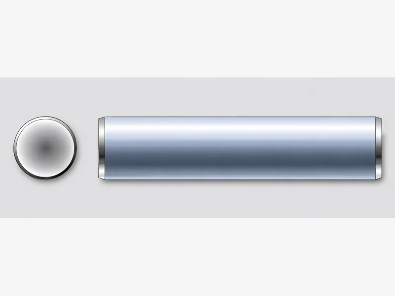
DIN 1469 is the gorge-form member of the three-groove press-fit pin family: the grooves run over half the pin length and end in a defined gorge, and the collected page tabulates three groove forms — Type A, Type B and Type C — with per-form groove length g and gorge dimensions m. Like every grooved pin it is driven into a plain drilled hole, not a reamed one: the displaced groove-edge metal flows back against the bore and holds by interference, so the joint tolerates hole tolerance, vibration and re-driving. Half-length grooving leaves a smooth half-shank, which is the point where the pin acts as a hinge or pivot pin on one side while staying locked in the other member. The collected table covers Φ2 to Φ25 — 13 sizes — with diameter limits, groove approach a, chamfer c ≈, the per-form g and m rows (Types A and B carry min/max limits; Type C prints a nominal gorge at roughly 1/2 IT14), the Type C radius r 2 and n rows, and the source's minimum double-shear values in kilonewtons. Lengths, materials and finishes are not printed by the collected specification and stay per RFQ. The source prints no legend distinguishing the A/B/C forms beyond the labels reproduced here.
| Standard | DIN 1469 — grooved pins, half length grooved with gorge (three-groove press-fit pin for drilled holes) |
|---|---|
| Size range | Nominal diameters Φ2 – Φ25 (13 sizes tabulated); length to order |
| Tabulated geometry | Per size: pin diameter d (max / min), groove approach a (max / min), chamfer c ≈; per groove form A/B/C: groove length g and gorge m; Type C radius r 2 and n |
| Gorge tolerance (Type C) | Nominal gorge m at ≈ 1/2 IT14, as printed by the source |
| Strength (source rows) | Minimum double shear in kN per size, as printed by the source — 2.85 kN at Φ2 rising to 370.1 kN at Φ25 |
| Materials / strength | Not tabulated by the collected specification beyond the source shear rows — per RFQ |
| Size | d — max=nominal size | d — min | a — max | a — min | c — ≈ | g — Type A max | g — Type A min | m — Type A min | m — Type A max | g — Type B max | g — Type B min | m — Type B max | m — Type B min | g — Type C ≈ | m — Type C Nominal (≈ 1/2 IT14) | m — Type C max | m — Type C min | r 2 — Type C ≈ | n — ≈ | Minimum double shear (kN) |
|---|---|---|---|---|---|---|---|---|---|---|---|---|---|---|---|---|---|---|---|---|
| Φ2 | 2 | 1.975 | 1.7 | 0.7 | 0.25 | - | - | - | - | 1.5 | 1.44 | 0.46 | 0.44 | 1 | 0.8 | 0.925 | 0.675 | 0.4 | 0.8 | 2.85 |
| Φ2.5 | 2.5 | 2.475 | 2 | 1 | 0.3 | - | - | - | - | 1.9 | 1.84 | 0.56 | 0.54 | 1.2 | 0.8 | 0.925 | 0.675 | 0.4 | 0.8 | 4.25 |
| Φ3 | 3 | 2.975 | 2 | 1 | 0.4 | 2.8 | 2.74 | 0.5 | 0.64 | 2.3 | 2.24 | 0.67 | 0.64 | 1.5 | 1 | 1.125 | 0.875 | 0.5 | 1 | 6.15 |
| Φ4 | 4 | 3.925 | 2.4 | 1.4 | 0.5 | 3.8 | 3.725 | 0.5 | 0.64 | 3.2 | 3.125 | 0.67 | 0.64 | 2.4 | 1.4 | 1.525 | 1.275 | 0.7 | 1.4 | 10.6 |
| Φ5 | 5 | 4.925 | 2.5 | 1.5 | 0.6 | 4.8 | 4.725 | 0.7 | 0.84 | 4 | 3.925 | 0.77 | 0.74 | 2.8 | 1.6 | 1.725 | 1.475 | 0.8 | 1.6 | 16.5 |
| Φ6 | 6 | 5.925 | 3 | 2 | 0.8 | 5.7 | 5.625 | 0.8 | 0.94 | 5 | 4.925 | 0.77 | 0.74 | 3.8 | 1.6 | 1.725 | 1.475 | 0.8 | 1.6 | 22.8 |
| Φ8 | 8 | 7.91 | 3 | 2 | 1 | 7.6 | 7.51 | 0.9 | 1.04 | 7 | 6.91 | 0.97 | 0.94 | 5 | 2 | 2.125 | 1.875 | 1 | 2 | 40.5 |
| Φ10 | 10 | 9.91 | 3.5 | 2.5 | 1.2 | 9.6 | 9.51 | 1.1 | 1.24 | 9 | 8.91 | 1.21 | 1.15 | 6.8 | 2.6 | 2.725 | 2.475 | 1.3 | 2.6 | 63.2 |
| Φ12 | 12 | 11.89 | 3.5 | 2.5 | 1.6 | 11.5 | 11.39 | 1.1 | 1.24 | 10 | 9.89 | 1.31 | 1.25 | 8.2 | 3 | 3.125 | 2.875 | 1.5 | 3 | 91 |
| Φ14 | 14 | 13.89 | 3.5 | 2.5 | 1.6 | 13.4 | 13.29 | 1.1 | 1.24 | 12 | 11.89 | 1.41 | 1.35 | 9.6 | 3 | 3.125 | 2.875 | 1.5 | 3 | 124 |
| Φ16 | 16 | 15.89 | 3.5 | 2.5 | 2 | 15.2 | 15.09 | 1.1 | 1.24 | 15 | 14.89 | 1.61 | 1.55 | 11 | 4 | 4.15 | 3.85 | 2 | 4 | 156.8 |
| Φ20 | 20 | 19.87 | 4 | 3 | 2.5 | 19 | 18.87 | 1.3 | 1.44 | 19 | 18.89 | 1.86 | 1.8 | 14 | 5 | 5.15 | 4.85 | 2.5 | 5 | 236.5 |
| Φ25 | 25 | 24.87 | 4 | 3 | 3 | 23.9 | 23.77 | 1.3 | 1.44 | 24 | 23.87 | 2.11 | 2.05 | 18 | 6 | 6.15 | 5.85 | 3 | 6 | 370.1 |
Materials
- Material and finish specified per RFQ — the collected specification table covers geometry and the source's strength rows only
Ordering & documentation
Documents
Shipments are backed by Mill Test Certificate (MTC), Dimensional Report, Salt Spray Test Report on request, with full batch traceability from raw material to finished product. Quality management follows the owner-confirmed compliance list: ISO 9001:2015, RoHS, REACH. Exact document sets are confirmed on the order.
Quotation
- The fastener family (DIN 1469 Grooved Pins, Half Length Grooved with Gorge (Types A/B/C)) plus the standard designation from your drawing — DIN / ISO / JIS / ASTM / ANSI, or a drawing for custom parts.
- Size (diameter and length), thread type (metric or inch), property class or grade, and coating or finish.
- Quantity per size and your target delivery date.
- Destination country, and any required documents (for example a mill test certificate) so the quote includes them.
Sample & supply
Minimum order quantities and lead times for this family are confirmed at quotation — send your sizes, grades and quantities on the RFQ and the quote will carry a firm schedule. Sample availability is confirmed with the quotation.
Storage & shipping
Parts are packed for export and shipped factory-direct to buyers in Europe, Asia, the Americas and the Middle East. Store fasteners dry and protected until installation, and keep coated parts in their packaging until use; specific packing and preservation requirements can be stated on the order and confirmed at quotation.
Frequently asked questions
Why choose a half-length grooved pin over a full-length groove?
Because the ungrooved half does different work. In a clevis, hinge or lever, one member needs the interference lock while the other only needs a smooth bearing surface — a full-length groove there adds friction and wear for nothing. DIN 1469 puts the three-groove lock over half the shank and ends it in a gorge, so the pin seats to a consistent depth and the smooth half pivots freely. Pick the groove form from the tabulated g and m rows against your housing: Type A and B carry tight min/max limits on both, Type C a nominal gorge at a general tolerance. Drill the hole to the size your tooling gives you — grooved pins are designed for drilled bores — and check the source's minimum double-shear row against the load with a real safety factor.
What is the MOQ and lead time for this pin type?
Commercial terms for this family are confirmed at quotation — state sizes, tolerance class and quantities on the RFQ for a firm schedule. Common diameters in this pin type are widely stocked; confirm the exact schedule against quantity and size mix at quotation.
Request a Quote
Get factory-direct pricing from the manufacturer.
What to include in your inquiry
- ✓ Standard and property class (e.g. DIN 912, ISO 4762, class 8.8) — or a drawing for custom parts.
- ✓ Sizes, lengths and thread type (metric or inch).
- ✓ Quantity per size and your target delivery date.
- ✓ Destination country, plus any coating or finish requirement.
- ✓ Any documents you need with the shipment (e.g. mill test certificate) so the quote includes them.
- ✓ Your inquiry goes straight to the factory team by email and gets a reply within 24 hours.
- ✓ Factory-direct pricing
- ✓ Standard and custom specifications
- ✓ Factory-direct export to buyers in Europe, Asia, the Americas and the Middle East
- ✓ Full fastener family support