
ASME B18.2.3.3M Heavy Hex Screws (Metric)
Metric heavy hex screws per ASME B18.2.3.3M — head and body dimension table for M12 to M36 with per-size thread pitches: body diameter Ds, width across flats/corners, head height K, wrenching height K1, washer face geometry.
Last updated: 2026-11
Specifications
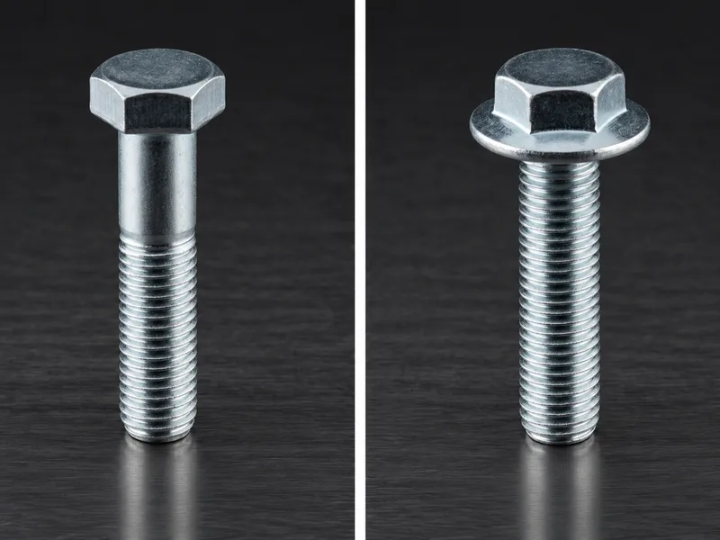
B18.2.3.3M is the metric heavy hex screw in the ASME B18.2.3 family: the same enlarged-head logic as the imperial heavy hex bolt, built for high-strength structural and heavy-equipment joints on a metric thread. The collected table runs M12 to M36 in the coarse metric pitches (M12 x 1.75 through M36 x 4), and the numbers show what "heavy" buys: a width across flats of 21 mm at M12 against 18 mm for a standard hex head — a 27 mm wrench size at M16, 34 at M20, 60 at M36 — with across-corners maxima (24.25 / 31.18 / 39.26 / 69.28 mm) sized so the wrenching faces stay usable on a head that carries the higher preloads these screws are selected for. Head height K max/min (7.76/7.24 at M12, 10.32/9.68 at M16) runs proportionally deeper than a standard hex head, and the washer-face columns (C 0.6/0.3 at M12, Dw min 19.6) define the seating that keeps the bearing pressure on the joint, not the fillet. Body diameter minima (11.73 at M12, 35.61 at M36) matter for thread-rolling blanks. Strength classes, proof loads and finish are not tabulated on the collected page — per RFQ.
| Standard | ASME B18.2.3.3M — metric heavy hex screws, coarse pitch, sizes M12 - M36 (M12 x 1.75, M14 x 2, M16 x 2, M20 x 2.5, M24 x 3, M30 x 3.5, M36 x 4) |
|---|---|
| Width across flats S | Max = nominal wrench size, min tolerance below (M12: 21 / 20.67; M16: 27 / 26.67; M20: 34 / 33; M36: 60 / 58.80) — the heavy-hex ladder, one size above standard hex at M12/M16 |
| Width across corners E | Max/min pairs (M12: 24.25 / 23.35; M20: 39.26 / 37.29; M36: 69.28 / 66.44) |
| Head height K | Max/min (M12: 7.76 / 7.24; M16: 10.32 / 9.68; M36: per the collected table) with wrenching height K1 min (M12: 5.2, M16: 7) |
| Body diameter Ds | Max = nominal, min for rolling blanks (M12: 11.73; M20: 19.67; M36: 35.61) |
| Washer face | Thickness C max/min (0.6/0.3 at M12, 0.8/0.4 from M16) and washer face diameter Dw min (M12: 19.6, M16: 25.3) |
| Not tabulated | Strength classes (property class / ASTM grade), proof loads, thread length B values, finish — per RFQ |
| Nominal Dia., D , and Thread Pitch | Body Diameter.,D s | Body Diameter.,D s | Width Across Flats,S | Width Across Flats,S | Width Across Corners, E | Width Across Corners, E | Head Height, K | Head Height, K | Wrenching Height, K 1 | Washer Face Thickness,C | Washer Face Thickness,C | Washer FaceDia.,D w |
|---|---|---|---|---|---|---|---|---|---|---|---|---|
| Nominal Dia., D , and Thread Pitch | Max | Min | Max | Min | Max | Min | Max | Min | Min | Max | Min | Min |
| ANSI B18.2.3.3M - M12 × 1.75 | 12 | 11.73 | 21 | 20.67 | 24.25 | 23.35 | 7.76 | 7.24 | 5.2 | 0.6 | 0.3 | 19.6 |
| ANSI B18.2.3.3M - M14 × 2 | 14 | 13.73 | 24 | 23.67 | 27.71 | 26.75 | 9.09 | 8.51 | 6.2 | 0.6 | 0.3 | 22.5 |
| ANSI B18.2.3.3M - M16 × 2 | 16 | 15.73 | 27 | 26.67 | 31.18 | 30.14 | 10.32 | 9.68 | 7 | 0.8 | 0.4 | 25.3 |
| ANSI B18.2.3.3M - M20 × 2.5 | 20 | 19.67 | 34 | 33 | 39.26 | 37.29 | 12.88 | 12.12 | 8.8 | 0.8 | 0.4 | 31.4 |
| ANSI B18.2.3.3M - M24 × 3 | 24 | 23.67 | 41 | 40 | 47.34 | 45.2 | 15.44 | 14.56 | 10.5 | 0.8 | 0.4 | 38 |
| ANSI B18.2.3.3M - M30 × 3.5 | 30 | 29.67 | 50 | 49 | 57.74 | 55.37 | 19.48 | 17.92 | 13.1 | 0.8 | 0.4 | 46.6 |
| ANSI B18.2.3.3M - M36 × 4 | 36 | 35.61 | 60 | 58.8 | 69.28 | 66.44 | 23.38 | 21.72 | 15.8 | 0.8 | 0.4 | 55.9 |
| All dimensions are in millimeters. Basic thread lengths, B, are the same as given in . Transition thread length, X, includes the length of incomplete threads and tolerances on grip gaging length and body length. It is intended for calculation purposes. For additional manufacturing and acceptance specifications, reference should be made to the Standard. | All dimensions are in millimeters. Basic thread lengths, B, are the same as given in . Transition thread length, X, includes the length of incomplete threads and tolerances on grip gaging length and body length. It is intended for calculation purposes. For additional manufacturing and acceptance specifications, reference should be made to the Standard. | All dimensions are in millimeters. Basic thread lengths, B, are the same as given in . Transition thread length, X, includes the length of incomplete threads and tolerances on grip gaging length and body length. It is intended for calculation purposes. For additional manufacturing and acceptance specifications, reference should be made to the Standard. | All dimensions are in millimeters. Basic thread lengths, B, are the same as given in . Transition thread length, X, includes the length of incomplete threads and tolerances on grip gaging length and body length. It is intended for calculation purposes. For additional manufacturing and acceptance specifications, reference should be made to the Standard. | All dimensions are in millimeters. Basic thread lengths, B, are the same as given in . Transition thread length, X, includes the length of incomplete threads and tolerances on grip gaging length and body length. It is intended for calculation purposes. For additional manufacturing and acceptance specifications, reference should be made to the Standard. | All dimensions are in millimeters. Basic thread lengths, B, are the same as given in . Transition thread length, X, includes the length of incomplete threads and tolerances on grip gaging length and body length. It is intended for calculation purposes. For additional manufacturing and acceptance specifications, reference should be made to the Standard. | All dimensions are in millimeters. Basic thread lengths, B, are the same as given in . Transition thread length, X, includes the length of incomplete threads and tolerances on grip gaging length and body length. It is intended for calculation purposes. For additional manufacturing and acceptance specifications, reference should be made to the Standard. | All dimensions are in millimeters. Basic thread lengths, B, are the same as given in . Transition thread length, X, includes the length of incomplete threads and tolerances on grip gaging length and body length. It is intended for calculation purposes. For additional manufacturing and acceptance specifications, reference should be made to the Standard. | All dimensions are in millimeters. Basic thread lengths, B, are the same as given in . Transition thread length, X, includes the length of incomplete threads and tolerances on grip gaging length and body length. It is intended for calculation purposes. For additional manufacturing and acceptance specifications, reference should be made to the Standard. | All dimensions are in millimeters. Basic thread lengths, B, are the same as given in . Transition thread length, X, includes the length of incomplete threads and tolerances on grip gaging length and body length. It is intended for calculation purposes. For additional manufacturing and acceptance specifications, reference should be made to the Standard. | All dimensions are in millimeters. Basic thread lengths, B, are the same as given in . Transition thread length, X, includes the length of incomplete threads and tolerances on grip gaging length and body length. It is intended for calculation purposes. For additional manufacturing and acceptance specifications, reference should be made to the Standard. | All dimensions are in millimeters. Basic thread lengths, B, are the same as given in . Transition thread length, X, includes the length of incomplete threads and tolerances on grip gaging length and body length. It is intended for calculation purposes. For additional manufacturing and acceptance specifications, reference should be made to the Standard. | All dimensions are in millimeters. Basic thread lengths, B, are the same as given in . Transition thread length, X, includes the length of incomplete threads and tolerances on grip gaging length and body length. It is intended for calculation purposes. For additional manufacturing and acceptance specifications, reference should be made to the Standard. |
- The trailing row repeats the source's usage note in every column (including its dangling 'as given in .' reference), carried verbatim; the header prints 'Body Diameter.,D s' with the source's punctuation.
Materials
- Metric heavy hex screws in this size class ship in carbon steel by property class (8.8 and up is the common structural range) and stainless A2/A4; the dimensions tabulated here are material-independent. State the required property class and any certificate level (EN 10204 3.1) explicitly on the RFQ — the collected page carries geometry only
Ordering & documentation
Documents
Shipments are backed by Mill Test Certificate (MTC), Dimensional Report, Salt Spray Test Report on request, with full batch traceability from raw material to finished product. Quality management follows the owner-confirmed compliance list: ISO 9001:2015, RoHS, REACH. Exact document sets are confirmed on the order.
Quotation
- The fastener family (ASME B18.2.3.3M Heavy Hex Screws (Metric)) plus the standard designation from your drawing — DIN / ISO / JIS / ASTM / ANSI, or a drawing for custom parts.
- Size (diameter and length), thread type (metric or inch), property class or grade, and coating or finish.
- Quantity per size and your target delivery date.
- Destination country, and any required documents (for example a mill test certificate) so the quote includes them.
Sample & supply
Minimum order quantity is 1,000–10,000 pieces depending on size. Stock items run 3–7 days. High-strength and custom parts run 15–25 days. Quantities or variants outside the standard range are confirmed at quotation.
Storage & shipping
Parts are packed for export and shipped factory-direct to buyers in Europe, Asia, the Americas and the Middle East. Store fasteners dry and protected until installation, and keep coated parts in their packaging until use; specific packing and preservation requirements can be stated on the order and confirmed at quotation.
Frequently asked questions
When does a B18.2.3.3M heavy hex screw replace a standard ISO 4017 hex bolt?
When the joint, not the catalogue, sets the wrench size. The collected table shows the mechanical difference directly: at M12 the heavy hex head presents 21 mm across flats against 18 mm for a standard hex — more bearing surface under the head and a larger, deeper hex for the high torques that high property classes need. In practice the substitution runs the other way: a drawing written around ASME heavy-hex practice (structural steelwork, heavy equipment, flanged assemblies) calls B18.2.3.3M by name, and a standard hex bolt should not be quietly fitted because it happens to thread in — the seating geometry (Dw, C) and head height differ along with the wrench size. Order by the drawing designation, pitch included.
Why does the table end at M36 and what does the trailing footnote row mean?
M36 is where the collected page stops tabulating: the B18.2.3.3M ladder in common supply runs M12 - M36, and larger metric heavy-hex sizes become engineered specials rather than catalogue items — quote them per RFQ with the joint data. The final row of the collected grid repeats the same usage note in every column (all dimensions in millimeters; basic thread lengths B referenced to the Standard; transition thread length X intended for calculation purposes) — it is the source page's own footnote layout, carried as printed. The note also flags that the thread-length values are not reproduced on this particular page — bring the required length band to the RFQ and we confirm against the Standard.
Related knowledge
- What Bolt Property Classes 8.8, 10.9 and 12.9 Encode — and When High Strength Stops Being the Right Choice
- Bolt Grade Selection: ISO 898-1 8.8/10.9/12.9 vs ASTM A307 and A325
- 8.8 vs 10.9 vs 12.9 Bolts: Strength, Hardness and Cost — What the Evidence Settles
- Calculating Bolt Preload and Clamp Force: Torque, Friction and Tightening Method
- How to Determine Tightening Torque and Choose a Tightening Method for a Bolted Joint
- Fastener Failure Modes: Which Fatigue, Creep and SCC Controls the Evidence Supports
- Hydrogen Embrittlement in High-Strength Bolts: Which Grades Need Controls, Which Coatings and Baking Schedules Are Acceptable, and What to Require Before the RFQ
Request a Quote
Get factory-direct pricing from the manufacturer.
What to include in your inquiry
- ✓ Standard and property class (e.g. DIN 912, ISO 4762, class 8.8) — or a drawing for custom parts.
- ✓ Sizes, lengths and thread type (metric or inch).
- ✓ Quantity per size and your target delivery date.
- ✓ Destination country, plus any coating or finish requirement.
- ✓ Any documents you need with the shipment (e.g. mill test certificate) so the quote includes them.
- ✓ Your inquiry goes straight to the factory team by email and gets a reply within 24 hours.
- ✓ Factory-direct pricing
- ✓ Standard and custom specifications
- ✓ Factory-direct export to buyers in Europe, Asia, the Americas and the Middle East
- ✓ Full fastener family support