
Spanner and Wrench Clearance Around Bolt Heads
Wrench-access clearance dimensions around hex bolt heads and nuts, M 3 to M 36 — clearance a/b/c, clearance hole, minimum plate thickness, G clearance, nominal spanner (A/F) size and square-drive sizes — in two tabulated layouts.
Last updated: 2026-11
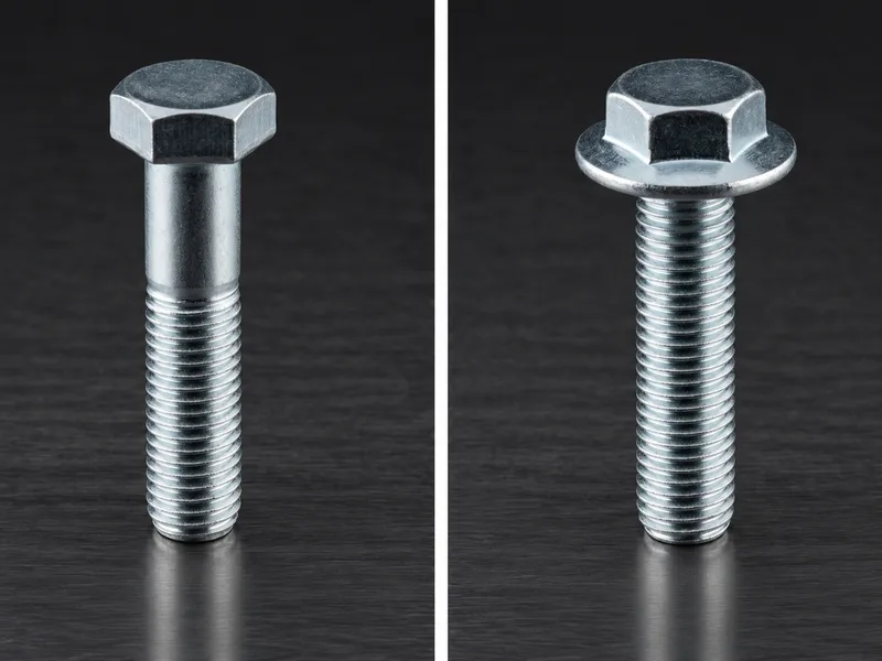
Specifications
Before a bolted joint exists on paper, it has to be assemble-able: a wrench needs room to swing, sockets need depth, and the plate behind the head needs a hole and enough thickness. This reference collects two independently tabulated clearance layouts from the collected page. The first layout covers M 3 to M 36 with, per size: the clearance hole diameter (M 8: 9.0 mm), the minimum plate thickness Min P, three clearance dimensions a, b and c around the head, the additional clearance G, the nominal spanner size across flats (M 12: A/F 19) and the square-drive size with drive square in parentheses (29 (12.5) at M 12). The second layout re-tabulates M 16 to M 36 with its own — substantially larger — Min P, clearance and spanner-adjacent values (M 24: Min P 84, clearances 48/40/55), reflecting a different layout convention on the source page; both layouts are carried verbatim side by side, and the values do not transfer between them. Use whichever layout your drawing or checking convention follows, and keep the wrench swing in mind: the a/b/c dimensions are the minimum envelope, not comfort clearances. Head dimensions themselves (widths across flats per ISO 4014/4017) are on the product pages — this page is the access envelope. Not-tabulated: counterbore depths, torque-access for powered tools — per RFQ.
| Layout 1 range | M 3 to M 36, 12 sizes: hole D, Min P, clearance a/b/c, G, spanner A/F, square drive H |
|---|---|
| Layout 2 range | M 16 to M 36, 5 sizes: Min P, clearance a/b/c, G, spanner A/F (independent tabulation, larger values) |
| Worked examples | Layout 1 M 10: hole 11.0, Min P 37, a/b/c 28/14/21, G 27, A/F 17, drive 27 (12.5); layout 2 M 20: Min P 64, a/b/c 48/28/42, G 48, A/F 32 |
| Units | mm; square-drive column prints the drive square in parentheses, e.g. 42 (20) |
| Not tabulated | Head dimensions per ISO 4014/4017, counterbores, tool-specific swing radii — per RFQ |
| Size | Hole D | Min P | Clearance | G | S Nominal Spanner Size A/F | H Square Drive | ||
|---|---|---|---|---|---|---|---|---|
| a | b | c | ||||||
| M3 | 3.4 | 14 | 10 | 8 | 10 | - | 5.5 | 14 (6.3) |
| M4 | 4.5 | 17 | 10 | 8 | 12 | 14 | 7 | 22 (10) |
| M5 | 5.5 | 20 | 10 | 8 | 12 | 14 | 8 | 22 (10) |
| M6 | 6.6 | 24 | 14 | 10 | 15 | 17 | 10 | 26 (12.5) |
| M8 | 9.0 | 30 | 18 | 12 | 18 | 22 | 13 | 26 (12.5) |
| M10 | 11.0 | 37 | 28 | 14 | 21 | 27 | 17 | 27 (12.5) |
| M12 | 13.5 | 42 | 30 | 16 | 22 | 30 | 19 | 29 (12.5) |
| M16 | 17.5 | 50 | 30 | 20 | 26 | 38 | 24 | 42 (20) |
| M20 | 22.0 | 60 | 32 | 22 | 32 | 46 | 30 | 47 (20) |
| M24 | 26.0 | 75 | 48 | 25 | 38 | 55 | 36 | 54 (20) |
| M30 | 33.0 | 94 | 60 | 30 | 48 | 70 | 46 | 70 (25) |
| M36 | 39.0 | 104 | 60 | 34 | 52 | 90 | 55 | 81 (25) |
- Row 1 (): the sub-header row assigns a/b/c to the Clearance column group; carried as the source prints it
- Row 2 (M3): M3 row prints G as "-" (no G clearance tabulated at M3); carried verbatim
| Size | Min P | Clearance | G | S Nominal Spanner Size A/F | ||
|---|---|---|---|---|---|---|
| a | b | c | ||||
| M16 | 56 | 30 | 25 | 38 | 27 | 27 |
| M20 | 64 | 48 | 28 | 42 | 48 | 32 |
| M24 | 84 | 48 | 40 | 55 | 65 | 41 |
| M30 | 98 | 60 | 45 | 65 | 77 | 50 |
| M36 | 112 | 60 | 45 | 70 | 81 | 60 |
- Row 1 (): sub-header assigns a/b/c to the Clearance group as printed
- Row 2 (M16): M16 G and spanner both print 27; M20 G prints 48 against a 32 spanner — values as printed, not normalized (the two layouts on this page are independent tabulations)
Materials
- Clearance geometry is independent of fastener material, but the joint around it is not: when you RFQ plates, brackets or welded assemblies that must accept these clearances, state the fastener size, the layout (1 or 2) your checking follows, and whether the access side is machined or as-rolled — Min P and the clearance envelope then drive the plate thickness and machining you order
Ordering & documentation
Documents
Shipments are backed by Mill Test Certificate (MTC), Dimensional Report, Salt Spray Test Report on request, with full batch traceability from raw material to finished product. Quality management follows the owner-confirmed compliance list: ISO 9001:2015, RoHS, REACH. Exact document sets are confirmed on the order.
Quotation
- The fastener family (Spanner and Wrench Clearance Around Bolt Heads) plus the standard designation from your drawing — DIN / ISO / JIS / ASTM / ANSI, or a drawing for custom parts.
- Size (diameter and length), thread type (metric or inch), property class or grade, and coating or finish.
- Quantity per size and your target delivery date.
- Destination country, and any required documents (for example a mill test certificate) so the quote includes them.
Sample & supply
Minimum order quantity is 1,000–10,000 pieces depending on size. Stock items run 3–7 days. High-strength and custom parts run 15–25 days. Quantities or variants outside the standard range are confirmed at quotation.
Storage & shipping
Parts are packed for export and shipped factory-direct to buyers in Europe, Asia, the Americas and the Middle East. Store fasteners dry and protected until installation, and keep coated parts in their packaging until use; specific packing and preservation requirements can be stated on the order and confirmed at quotation.
Frequently asked questions
Why are there two different clearance tables for the same M 16 - M 36 sizes?
Because the collected page tabulates two independent layout conventions side by side, and we carry both verbatim. Layout 1 gives the compact envelope (M 16: Min P 50, clearance 30/20/26, A/F 24); layout 2 gives a generous envelope (M 16: Min P 56, clearance 30/25/38, G 27 against spanner 27). The numbers differ exactly where layout philosophy differs — minimum plate thickness and the room the wrench gets to swing. Neither is wrong; each matches a different checking practice. The failure mode to avoid is mixing them: reading Min P from layout 2 with clearances from layout 1 produces a joint that neither fits nor checks. Pick the layout your drawing references, use one table throughout, and flag which one you used when you RFQ the mating plates.
How much clearance does a wrench actually need around a bolt head?
Read it off the a/b/c columns for the fastener size, then add tool allowance. For the common mid-range: M 10 needs a 28 x 14 x 21 mm envelope (layout 1) around an 11.0 mm hole, M 16 needs 30 x 20 x 26 — the "a" dimension is the swing direction and dominates, which is why it grows fastest in layout 2 (M 24: 48). A ring spanner needs almost exactly the tabulated envelope; an open-end or socket with extension needs more, especially in "a". The G column is additional clearance beyond a/b/c where the tabulation carries it (blank or "-" at M 3 in layout 1). Design the access first, then confirm the hole and plate: hole D and Min P columns give the minimums (M 20: 22.0 hole, Min P 60 in layout 1 vs 64 in layout 2). For assemblies where access is tight, send the stack-up with the RFQ so assembly feasibility is checked before order.
Related knowledge
- What Bolt Property Classes 8.8, 10.9 and 12.9 Encode — and When High Strength Stops Being the Right Choice
- Bolt Grade Selection: ISO 898-1 8.8/10.9/12.9 vs ASTM A307 and A325
- 8.8 vs 10.9 vs 12.9 Bolts: Strength, Hardness and Cost — What the Evidence Settles
- Calculating Bolt Preload and Clamp Force: Torque, Friction and Tightening Method
- How to Determine Tightening Torque and Choose a Tightening Method for a Bolted Joint
- Fastener Failure Modes: Which Fatigue, Creep and SCC Controls the Evidence Supports
- Hydrogen Embrittlement in High-Strength Bolts: Which Grades Need Controls, Which Coatings and Baking Schedules Are Acceptable, and What to Require Before the RFQ
Request a Quote
Get factory-direct pricing from the manufacturer.
What to include in your inquiry
- ✓ Standard and property class (e.g. DIN 912, ISO 4762, class 8.8) — or a drawing for custom parts.
- ✓ Sizes, lengths and thread type (metric or inch).
- ✓ Quantity per size and your target delivery date.
- ✓ Destination country, plus any coating or finish requirement.
- ✓ Any documents you need with the shipment (e.g. mill test certificate) so the quote includes them.
- ✓ Your inquiry goes straight to the factory team by email and gets a reply within 24 hours.
- ✓ Factory-direct pricing
- ✓ Standard and custom specifications
- ✓ Factory-direct export to buyers in Europe, Asia, the Americas and the Middle East
- ✓ Full fastener family support