
ASME B18.31.1M Metric Continuous-Thread Studs (Double-End, Full Body)
Metric studs per ASME B18.31.1M — thread-length tables for the continuous-thread (full body) and double-end reduced-body configurations, M1.6 to M100: thread length B min/max per stud-length band, tap end BM, runout U = 2P, and nominal length ranges with increments.
Last updated: 2026-11
Specifications
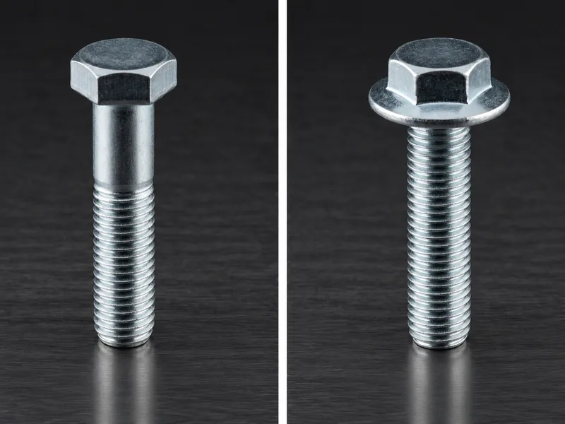
B18.31.1M governs metric studs, and the collected page carries both configurations buyers actually order: Table 1 the continuous-thread stud (threaded full length, no body) and Table 2 the double-end stud with reduced body and a defined tap end. The geometry is a ladder from M1.6 to M100, and the columns do the engineering: thread length B min/max per length band — LT ≤ 250 / 250 < LT ≤ 400 / LT > 400 for the continuous stud, L ≤ 125 / 125 < L ≤ 200 / L > 200 for the double-end — so a longer stud automatically gets proportionally longer engagement per end. At M12 (pitch 1.75), the continuous table runs B 18.2/20.3 in the short band up through the LT > 400 band as tabulated; at M100 (pitch 6) only the longest band applies, B 225/237. The U max = 2P column is the thread runout allowance — two pitches of incomplete thread per end, the number a machinist needs when the stud must bottom in a tapped hole. The double-end table adds BM, the tap end length (2.1-2.7 at M1.6 up to 148-152 at M100), the screw-in end that the flange or housing receives. Nominal length ranges and increments (25-50 by 5 at the small end up to ≥480 by 20 at the top) close each row. Property classes and materials are not tabulated — per RFQ.
| Standard | ASME B18.31.1M — metric studs, M1.6 - M100; Table 1 continuous-thread (full body), Table 2 double-end with reduced body |
|---|---|
| Thread length B (continuous) | Min/max per stud-length band LT ≤ 250 / 250 < LT ≤ 400 / LT > 400 (M1.6: 9.2/9.9 short band; M100: 225/237 in the LT > 400 band); cells print "..." where a band does not apply |
| Thread length B (double-end) | Min/max per band L ≤ 125 / 125 < L ≤ 200 / L > 200, same ladder logic per diameter |
| Tap end BM | Double-end only: tap end length range per diameter (M1.6: 2.1-2.7 through M100: 148-152) — the screw-in end |
| Runout U | U max = 2P (2 x pitch): 0.7 at M1.6 up to 12 at M100 — the incomplete-thread allowance per end |
| Nominal lengths | Range and increments per diameter (25-50 by 5 at the small end; ≥480 by 20 at M100); order within the tabulated ladder |
| Not tabulated | Property classes (B7/L7 metric counterparts), materials, finish — per RFQ |
| Nominal Size | Nominal Size | Thread Length, B | Thread Length, B | Thread Length, B | Thread Length, B | Thread Length, B | Thread Length, B | Thread Length, B | Nominal Length, LT | Nominal Length, LT |
|---|---|---|---|---|---|---|---|---|---|---|
| Diameter, D | Pitch, P | LT ≤ 250 | LT ≤ 250 | 250 < LT ≤ 400 | 250 < LT ≤ 400 | LT > 400 | LT > 400 | Umax p 2P | Nominal Length, LT | Nominal Length, LT |
| Diameter, D | Pitch, P | Min. | Max. | Min. | Max. | Min. | Max. | Umax p 2P | Range | Increments |
| M1.6 | 0.35 | 9.2 | 9.9 | ... | ... | ... | ... | 0.7 | 25-50 | 5 |
| M2 | 0.4 | 10 | 10.8 | ... | ... | ... | ... | 0.8 | 25-50 | 5 |
| M2.5 | 0.45 | 11 | 11.9 | ... | ... | ... | ... | 0.9 | 30-50 | 5 |
| M3 | 0.5 | 12 | 13 | ... | ... | ... | ... | 1 | 30-50 | 5 |
| M4 | 0.7 | 14 | 15.4 | ... | ... | ... | ... | 1.4 | 35-90 | 5 |
| M5 | 0.8 | 16 | 17.6 | ... | ... | ... | ... | 1.6 | 40-90 | 5 |
| M6 | 1 | 18 | 20 | 24 | 26 | ... | ... | 2 | 50-90 | 5 |
| M6 | 1 | 18 | 20 | 24 | 26 | ... | ... | 2 | 100-160 | 10 |
| M8 | 1.25 | 18 | 20.5 | 24 | 26.5 | ... | ... | 2.5 | 50-90 | 5 |
| M8 | 1.25 | 18 | 20.5 | 24 | 26.5 | ... | ... | 2.5 | 100-160 | 10 |
| M8 | 1.25 | 18 | 20.5 | 24 | 26.5 | ... | ... | 2.5 | ≥ 180 | 20 |
| M10 | 1.5 | 26 | 29 | 32 | 35 | 45 | 48 | 3 | 60-160 | 10 |
| M10 | 1.5 | 26 | 29 | 32 | 35 | 45 | 48 | 3 | ≥ 180 | 20 |
| M12 | 1.75 | 30 | 33.5 | 36 | 39.5 | 49 | 52.5 | 3.5 | 60-160 | 10 |
| M12 | 1.75 | 30 | 33.5 | 36 | 39.5 | 49 | 52.5 | 3.5 | ≥ 180 | 20 |
| M14 [Note (5)] | 2 | 34 | 38 | 40 | 44 | 53 | 57 | 4 | 80-160 | 10 |
| M14 [Note (5)] | 2 | 34 | 38 | 40 | 44 | 53 | 57 | 4 | ≥ 180 | 20 |
| M16 | 2 | 38 | 42 | 44 | 48 | 57 | 61 | 4 | 90-160 | 10 |
| M16 | 2 | 38 | 42 | 44 | 48 | 57 | 61 | 4 | ≥ 180 | 20 |
| M20 | 2.5 | 46 | 51 | 52 | 57 | 65 | 70 | 5 | 100-160 | 10 |
| M20 | 2.5 | 46 | 51 | 52 | 57 | 65 | 70 | 5 | ≥ 180 | 20 |
| M24 | 3 | 54 | 60 | 60 | 66 | 73 | 79 | 6 | 130-160 | 10 |
| M24 | 3 | 54 | 60 | 60 | 66 | 73 | 79 | 6 | ≥ 180 | 20 |
| M30 | 3.5 | 66 | 73 | 72 | 79 | 85 | 92 | 7 | 150-160 | 10 |
| M30 | 3.5 | 66 | 73 | 72 | 79 | 85 | 92 | 7 | ≥ 180 | 20 |
| M36 | 4 | 78 | 86 | 84 | 92 | 97 | 105 | 8 | ≥ 200 | 20 |
| M42 | 4.5 | 90 | 99 | 96 | 105 | 109 | 118 | 9 | ≥ 240 | 20 |
| M48 | 5 | ... | ... | 108 | 118 | 121 | 131 | 10 | ≥ 280 | 20 |
| M56 | 5.5 | ... | ... | 124 | 135 | 137 | 148 | 11 | ≥ 300 | 20 |
| M64 | 6 | ... | ... | 140 | 152 | 153 | 165 | 12 | ≥340 | 20 |
| M72 | 6 | ... | ... | 156 | 168 | 169 | 181 | 12 | ≥380 | 20 |
| M80 | 6 | ... | ... | 172 | 184 | 185 | 197 | 12 | ≥400 | 20 |
| M90 | 6 | ... | ... | ... | ... | 205 | 217 | 12 | ≥440 | 20 |
| M100 | 6 | ... | ... | ... | ... | 225 | 237 | 12 | ≥480 | 20 |
- Cells print '...' where a stud-length band does not apply to the diameter; the three-row source header is carried as three leading label cells with repeated text, verbatim.
| Nominal Size | Nominal Size | Tap End Length BM | Thread Length, B | Thread Length, B | Thread Length, B | Thread Length, B | Thread Length, B | Thread Length, B | Thread Length, B | Nominal Length, L | Nominal Length, L |
|---|---|---|---|---|---|---|---|---|---|---|---|
| Diameter, D | Pitch, P | Tap End Length BM | L ≤ 125 | L ≤ 125 | 125 < L ≤ 200 | 125 < L ≤ 200 | L > 200 | L > 200 | Umax p 2P | Nominal Length, L | Nominal Length, L |
| Diameter, D | Pitch, P | Tap End Length BM | Min. | Max. | Min. | Max. | Min. | Max. | Umax p 2P | Range | Increments |
| M1.6 | 0.35 | 2.1-2.7 | 9.2 | 9.9 | ... | ... | ... | ... | 0.7 | 25-50 | 5 |
| M2 | 0.4 | 2.7-3.3 | 10 | 10.8 | ... | ... | ... | ... | 0.8 | 25-50 | 5 |
| M2.5 | 0.45 | 3.375-4.125 | 11 | 11.9 | ... | ... | ... | ... | 0.9 | 30-50 | 5 |
| M3 | 0.5 | 4.125-4.875 | 12 | 13 | ... | ... | ... | ... | 1 | 30-50 | 5 |
| M4 | 0.7 | 5.625-6.375 | 14 | 15.4 | ... | ... | ... | ... | 1.4 | 35-90 | 5 |
| M5 | 0.8 | 7.05-7.95 | 16 | 17.6 | ... | ... | ... | ... | 1.6 | 40-90 | 5 |
| M6 | 1 | 8.55-9.45 | 18 | 20 | 24 | 26 | ... | ... | 2 | 50-90 | 5 |
| M6 | 1 | 8.55-9.45 | 18 | 20 | 24 | 26 | ... | ... | 2 | 100-160 | 10 |
| M8 | 1.25 | 11.45-12.55 | 18 | 20.5 | 24 | 26.5 | ... | ... | 2.5 | 50-90 | 5 |
| M8 | 1.25 | 11.45-12.55 | 18 | 20.5 | 24 | 26.5 | ... | ... | 2.5 | 100-160 | 10 |
| M8 | 1.25 | 11.45-12.55 | 18 | 20.5 | 24 | 26.5 | ... | ... | 2.5 | ≥ 180 | 20 |
| M10 | 1.5 | 14.45-15.55 | 26 | 29 | 32 | 35 | 45 | 48 | 3 | 60-160 | 10 |
| M10 | 1.5 | 14.45-15.55 | 26 | 29 | 32 | 35 | 45 | 48 | 3 | ≥ 180 | 20 |
| M12 | 1.75 | 17.45-18.55 | 30 | 33.5 | 36 | 39.5 | 49 | 52.5 | 3.5 | 60-160 | 10 |
| M12 | 1.75 | 17.45-18.55 | 30 | 33.5 | 36 | 39.5 | 49 | 52.5 | 3.5 | ≥ 180 | 20 |
| M14 [Note (5)] | 2 | 20.35-21.65 | 34 | 38 | 40 | 44 | 53 | 57 | 4 | 80-160 | 10 |
| M14 [Note (5)] | 2 | 20.35-21.65 | 34 | 38 | 40 | 44 | 53 | 57 | 4 | ≥ 180 | 20 |
| M16 | 2 | 23.35-30.65 | 38 | 42 | 44 | 48 | 57 | 61 | 4 | 90-160 | 10 |
| M16 | 2 | 23.35-30.65 | 38 | 42 | 44 | 48 | 57 | 61 | 4 | ≥ 180 | 20 |
| M20 | 2.5 | 29.35-30.65 | 46 | 56 | 52 | 57 | 65 | 70 | 5 | 100-160 | 10 |
| M20 | 2.5 | 29.35-30.65 | 46 | 56 | 52 | 57 | 65 | 70 | 5 | ≥ 180 | 20 |
| M24 | 3 | 35.2-36.8 | 54 | 60 | 60 | 66 | 73 | 79 | 6 | 130-160 | 10 |
| M24 | 3 | 35.2-36.8 | 54 | 60 | 60 | 66 | 73 | 79 | 6 | ≥ 180 | 20 |
| M30 | 3.5 | 43.75-46.25 | 66 | 73 | 72 | 79 | 85 | 92 | 7 | 150-160 | 10 |
| M30 | 3.5 | 43.75-46.25 | 66 | 73 | 72 | 79 | 85 | 92 | 7 | ≥ 180 | 20 |
| M36 | 4 | 52.5-55.5 | 78 | 86 | 84 | 92 | 97 | 105 | 8 | ≥ 200 | 20 |
| M42 | 4.5 | 61.5-64.5 | 90 | 99 | 96 | 105 | 109 | 118 | 9 | ≥ 240 | 20 |
| M48 | 5 | 70.5-73.5 | ... | ... | 108 | 118 | 121 | 131 | 10 | ≥ 280 | 20 |
| M56 | 5.5 | 82.25-85.75 | ... | ... | 124 | 135 | 137 | 148 | 11 | ≥ 300 | 20 |
| M64 | 6 | 94.5-97.5 | ... | ... | 140 | 152 | 153 | 165 | 12 | ≥340 | 20 |
| M72 | 6 | 106.5-109.5 | ... | ... | 156 | 168 | 169 | 181 | 12 | ≥380 | 20 |
| M80 | 6 | 118.5-121.5 | ... | ... | 172 | 184 | 185 | 197 | 12 | ≥400 | 20 |
| M90 | 6 | 133-137 | ... | ... | ... | ... | 205 | 217 | 12 | ≥440 | 20 |
| M100 | 6 | 148-152 | ... | ... | ... | ... | 225 | 237 | 12 | ≥480 | 20 |
- Cells print '...' where a thread-length band does not apply to the diameter; three-row source header carried verbatim.
Materials
- Metric studs ship in carbon steel by property class (the flange-stud classes buyers usually mean — B7/L7 equivalents and their metric designations — are ordered by class and temperature rating) and stainless A2/A4. State the configuration explicitly on the RFQ — continuous thread or double-end with tap end — because the two are dimensioned differently and are not interchangeable in a tapped hole
Ordering & documentation
Documents
Shipments are backed by Mill Test Certificate (MTC), Dimensional Report, Salt Spray Test Report on request, with full batch traceability from raw material to finished product. Quality management follows the owner-confirmed compliance list: ISO 9001:2015, RoHS, REACH. Exact document sets are confirmed on the order.
Quotation
- The fastener family (ASME B18.31.1M Metric Continuous-Thread Studs (Double-End, Full Body)) plus the standard designation from your drawing — DIN / ISO / JIS / ASTM / ANSI, or a drawing for custom parts.
- Size (diameter and length), thread type (metric or inch), property class or grade, and coating or finish.
- Quantity per size and your target delivery date.
- Destination country, and any required documents (for example a mill test certificate) so the quote includes them.
Sample & supply
Minimum order quantity is 1,000–10,000 pieces depending on size. Stock items run 3–7 days. High-strength and custom parts run 15–25 days. Quantities or variants outside the standard range are confirmed at quotation.
Storage & shipping
Parts are packed for export and shipped factory-direct to buyers in Europe, Asia, the Americas and the Middle East. Store fasteners dry and protected until installation, and keep coated parts in their packaging until use; specific packing and preservation requirements can be stated on the order and confirmed at quotation.
Frequently asked questions
Continuous-thread or double-end stud — how do the two tables differ in practice?
By where the thread needs to be. The continuous-thread stud (Table 1) is threaded over its whole length — the choice for through-studs with nuts both ends, where position along the length is adjusted with the nuts. The double-end stud (Table 2) carries a defined tap end BM that screws into a tapped flange or housing, a plain or reduced body in the middle, and a nut end; the collected table dimensions the tap end separately per diameter (2.1-2.7 mm at M1.6 up to 148-152 at M100) because engagement in the tapped hole is a controlled fit, not a leftover. The length-band columns also differ — continuous studs key off total stud length LT, double-ends off nominal length L — and in both tables the B min/max pairs widen with the band: longer stud, proportionally longer thread per end. Order by configuration, diameter and pitch together ("M12 x 1.75 double-end x 60"), and name which end is the tap end.
What does U max = 2P mean at the thread runout?
It is the allowance for the incomplete thread where the rolled or cut thread dies out — at most two pitches of it. At M12 (pitch 1.75) that is up to 3.5 mm of partial thread per end; at M100 (pitch 6), 12 mm. The figure matters in two real situations: a stud screwed to the bottom of a blind tapped hole, where the runout must not be counted as engagement (the full-thread length B min already excludes it — that is why the tables give min/max), and a nut run-up, where the last two pitches may not carry full form. Read the U column as the boundary between "threaded" and "almost threaded" and neither gauge the stud nor set the nut against the runout itself.
Related knowledge
- What Bolt Property Classes 8.8, 10.9 and 12.9 Encode — and When High Strength Stops Being the Right Choice
- Bolt Grade Selection: ISO 898-1 8.8/10.9/12.9 vs ASTM A307 and A325
- 8.8 vs 10.9 vs 12.9 Bolts: Strength, Hardness and Cost — What the Evidence Settles
- Calculating Bolt Preload and Clamp Force: Torque, Friction and Tightening Method
- How to Determine Tightening Torque and Choose a Tightening Method for a Bolted Joint
- Fastener Failure Modes: Which Fatigue, Creep and SCC Controls the Evidence Supports
- Hydrogen Embrittlement in High-Strength Bolts: Which Grades Need Controls, Which Coatings and Baking Schedules Are Acceptable, and What to Require Before the RFQ
Request a Quote
Get factory-direct pricing from the manufacturer.
What to include in your inquiry
- ✓ Standard and property class (e.g. DIN 912, ISO 4762, class 8.8) — or a drawing for custom parts.
- ✓ Sizes, lengths and thread type (metric or inch).
- ✓ Quantity per size and your target delivery date.
- ✓ Destination country, plus any coating or finish requirement.
- ✓ Any documents you need with the shipment (e.g. mill test certificate) so the quote includes them.
- ✓ Your inquiry goes straight to the factory team by email and gets a reply within 24 hours.
- ✓ Factory-direct pricing
- ✓ Standard and custom specifications
- ✓ Factory-direct export to buyers in Europe, Asia, the Americas and the Middle East
- ✓ Full fastener family support