
ASME B18.6.3 Micro Machine Screws (Cross-Recess and Slotted)
Micro machine screw data per ASME B18.6.3 — cross-recess dimensions by type (I, II, III, VI) with driver sizes and penetration gaging depths from #0 up, plus slotted micro head dimensions from #0000 (0.021" basic diameter) to 3/8": head diameter, height, slot width/depth, gaging diameter.
Last updated: 2026-11
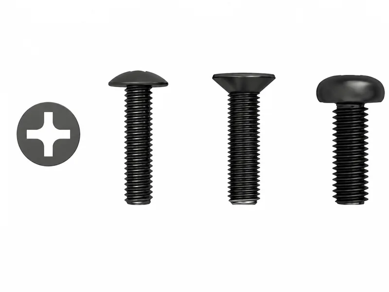
Specifications
The micro end of the machine-screw range lives on its own data because ordinary screw gauges stop applying: the collected page tabulates two tables that a micro-assembly buyer actually needs. Table 1 is the cross-recess fork — Types I, II, III and VI — per nominal size from #0 (0.060" basic diameter) up through 3/4": for each type, the recess diameter M, the driver size (a Type I #0 takes driver 0; a Type VI 3/4" takes T60), and the recess penetration gaging depth P max/min, the measurement that decides whether the driver bottoms out or cams out — the practical difference between an assembly line that runs and one that strips recesses. Type III (the square recess / across-flats column) and the Type VI TORX-compatible sizes (T5 at #1 up to T60) show which driver system each size actually carries, with "..." placeholders where a type does not apply to a size. Table 2 drops to the slotted micro heads from #0000 (0.0210") — head diameter A, head height H, slot width J and depth T max/min, and the gaging diameter G — the columns a micro-screw inspection plan is written around. The source page carries OCR-era print defects ("Falla way" for the fall-away column, split decimals like "0.0 55"); they are carried verbatim and flagged. Strength and materials are not tabulated — per RFQ.
| Standard | ASME B18.6.3 — micro machine screws; Table 1 cross-recess types I / II / III / VI, #0 - 3/4"; Table 2 slotted heads, #0000 - 3/8" |
|---|---|
| Cross-recess fork | Per size: Type I recess dia M ref + driver size + P max/min; Type II recess dia min + driver + P; Type III across flats M ref + driver + P; Type VI recess dia min + TORX driver size (T5 at #1 through T60 at 3/4") + P and fall-away max |
| Driver sizes | Type I/II numeric driver sizes (0 at #0/#1 up to 5 at 5/8" - 3/4"); Type VI TORX-compatible (T5 - T60); Type III R/S coded sizes as tabulated |
| Penetration gaging depth P | Max/min pairs per type and size (Type I #0: 0.036/0.020) — the go/no-go depth that separates full driver engagement from cam-out |
| Slotted micro heads | #0000 (0.0210" basic dia): A 0.040/0.035, H 0.009 ref, J 0.008/0.005, T 0.008/0.004 — up to 3/8": A 0.717/0.662, J 0.094/0.081, G 0.638; cells print [Note (4)] where the dimension is note-covered |
| Gaging diameter G | Tabulated from #0 (0.074) upward — the head-projection gaging circle for micro inspection; [Note (4)] below #0 |
| Not tabulated | Strength, materials, finish, thread data — per RFQ |
| Nominal Size or Basic Screw Diameter [Notes (1), (2), (3)] | Nominal Size or Basic Screw Diameter [Notes (1), (2), (3)] | Type I | Type I | Type I | Type I | Type II | Type II | Type II | Type II | Type III | Type III | Type III | Type III | Type VI | Type VI | Type VI | Type VI | Type VI |
|---|---|---|---|---|---|---|---|---|---|---|---|---|---|---|---|---|---|---|
| Nominal Size or Basic Screw Diameter [Notes (1), (2), (3)] | Nominal Size or Basic Screw Diameter [Notes (1), (2), (3)] | Recess Dia., M, Ref. | Driver Size | Recess Penetration Gaging Depth, P | Recess Penetration Gaging Depth, P | Recess Dia., Min. | Driver Size | Recess Penetration Gaging Depth, P | Recess Penetration Gaging Depth, P | Across Flats, M, Ref. | Driver Size (4) | Recess Penetration Gaging Depth, P | Recess Penetration Gaging Depth, P | Recess Dia., Min. | Driver Size | Recess Penetration Gaging Depth, P | Recess Penetration Gaging Depth, P | Falla way |
| Nominal Size or Basic Screw Diameter [Notes (1), (2), (3)] | Nominal Size or Basic Screw Diameter [Notes (1), (2), (3)] | Recess Dia., M, Ref. | Driver Size | Max. | Min. | Recess Dia., Min. | Driver Size | Max. | Min. | Across Flats, M, Ref. | Driver Size (4) | Max. | Min. | Recess Dia., Min. | Driver Size | Max. | Min. | Max. |
| #0 | 0.060 | 0.062 | 0 | 0.036 | 0.020 | 0.062 | 0 | 0.037 | 0.021 | ... | ... | ... | ... | ... | ... | ... | ... | ... |
| #1 | 0.073 | 0.070 | 0 | 0.044 | 0.028 | 0.070 | 0 | 0.045 | 0.029 | ... | . .. | . .. | . .. | 0.058 | T5 | 0.017 | 0.012 | 0.010 |
| #2 | 0.086 | 0.096 | 1 | 0.056 | 0.040 | 0.096 | 1 | 0.053 | 0.037 | 0.050 | 00 | 0.033 | 0.028 | 0.069 | T6 | 0.022 | 0.017 | 0.014 |
| #3 | 0.099 | 0.100 | 1 | 0.061 | 0.045 | 0.100 | 1 | 0.058 | 0.042 | 0.070 | 0 | 0.038 | 0.028 | 0.094 | T8 | 0.025 | 0.020 | 0.019 |
| #4 | 0.112 | 0.122 | 1 | 0.082 | 0.066 | 0.122 | 1 | 0.079 | 0.063 | 0.07 | 0 | 0.038 | 0.028 | 0.094 | T8 | 0.033 | 0.028 | 0.019 |
| #5 | 0.125 | 0.148 | 2 | 0.075 | 0.052 | 0.148 | 2 | 0.071 | 0.053 | 0.091 | 1S | 0.0 55 | 0.040 | 0.111 | T10 | 0.045 | 0.035 | 0.022 |
| #6 | 0.138 | 0.168 | 2 | 0.095 | 0.072 | 0.168 | 2 | 0.091 | 0.073 | 0.091 | 1S | 0.055 | 0.040 | 0.111 | TlO | 0.045 | 0.035 | 0.022 |
| #7 | 0.151 | 0.176 | 2 | 0.103 | 0.080 | 0.176 | 2 | 0.099 | 0.081 | 0.091 | 1R | 0.065 | 0.050 | 0.132 | T15 | 0.045 | 0.035 | 0.022 |
| #8 | 0.164 | 0.182 | 2 | 0.110 | 0.087 | 0.182 | 2 | 0.107 | 0.089 | 0.112 | 2S | 0.063 | 0.048 | 0.132 | T15 | 0.051 | 0.040 | 0.026 |
| #10 | 0.190 | 0.198 | 2 | 0.125 | 0.102 | 0.198 | 2 | 0.122 | 0.104 | 0.112 | 2R | 0.075 | 0.060 | 0.155 | T20 | 0.065 | 0.050 | 0.031 |
| #12 | 0.216 | 0.262 | 3 | 0.139 | 0.116 | 0.262 | 3 | 0.136 | 0.118 | 0.133 | 3R | 0.095 | 0.080 | 0. 178 | T2 5 | 0.070 | 0.055 | 0.036 |
| #14 | 0.242 | 0.276 | 3 | 0.154 | 0.131 | 0.276 | 3 | 0.151 | 0.133 | 0.133 | 3R | 0.095 | 0.080 | 0.200 | T27 | 0.080 | 0.065 | 0.040 |
| 1/4" | 0.250 | 0.276 | 3 | 0.154 | 0.131 | 0.276 | 3 | 0.151 | 0.133 | 0.133 | 3R | 0.095 | 0.080 | 0.200 | T27 | 0.090 | 0.075 | 0.04 |
| 16" | 0.268 | 0.296 | 3 | 0.174 | 0.151 | 0.296 | 3 | 0.171 | 0.153 | 0.133 | 3R | 0.095 | 0.080 | 0. 221 | T30 | 0.070 | 0.055 | 0.042 |
| 18" | 0.294 | 0.358 | 4 | 0.196 | 0.174 | 0.358 | 4 | 0.193 | 0.175 | 0.191 | 4R | 0.100 | 0.085 | 0. 221 | T30 | 0.090 | 0.075 | 0.042 |
| 5/16" | 0.313 | 0.358 | 4 | 0.196 | 0.174 | 0.358 | 4 | 0.193 | 0.175 | 0.191 | 4R | 0.100 | 0.085 | 0. 266 | T40 | 0.105 | 0.087 | 0.047 |
| 20" | 0.320 | 0.372 | 4 | 0.210 | 0.188 | 0.372 | 4 | 0.206 | 0.188 | 0.191 | 4R | 0.100 | 0.085 | 0.266 | T40 | 0.115 | 0.095 | 0.047 |
| 24" | 0.372 | 0.386 | 4 | 0.225 | 0.203 | 0.386 | 4 | 0.222 | 0. 204 | 0.191 | 4R | 0.100 | 0.085 | 0.266 | T40 | 0.125 | 0.105 | 0.047 |
| 3/8" | 0.375 | 0.386 | 4 | 0. 225 | 0.203 | 0.386 | 4 | 0.222 | 0.204 | 0.191 | 4R | 0.100 | 0.085 | 0. 266 | T40 | 0.135 | 0.115 | 0.047 |
| 7/16" | 0.438 | 0.402 | 4 | 0.241 | 0.219 | 0.402 | 4 | 0.238 | 0.220 | .. . | ... | . .. | . .. | 0.352 | T50 | 0.125 | 0.105 | 0.062 |
| 1/2" | 0.500 | 0.4 18 | 4 | 0. 256 | 0.234 | 0.418 | 4 | 0.253 | 0.235 | ... | . . . | . .. | . .. | 0.352 | T50 | 0.135 | 0.120 | 0.062 |
| 9/16" | 0.563 | 0.443 | 4 | 0.280 | 0.258 | 0.440 | 4 | 0.276 | 0.258 | ... | . . . | . .. | . .. | 0.446 | T55 | 0.160 | 0.140 | 0.078 |
| 5/8" | 0.625 | 0.565 | 5 | 0.309 | 0.283 | 0.566 | 5 | 0.307 | 0.286 | ... | ... | . .. | . .. | 0.446 | T55 | 0.160 | 0.140 | 0.078 |
| 3/4" | 0.750 | 0.628 | 5 | 0.373 | 0.347 | 0.630 | 5 | 0.372 | 0.351 | .. . | . .. | . . . | . .. | 0.529 | T60 | 0.230 | 0.205 | 0.093 |
- The source page carries OCR-style print defects carried verbatim, not normalized: 'Falla way' for the fall-away column, spaced placeholder cells ('. ..', '.. .', '. . .') where Type III data does not apply, and split decimals in several cells ('0.0 55', '0. 225', '0. 178', 'T2 5', 'TlO').
| Nominal Size or Basic Screw Diameter | Nominal Size or Basic Screw Diameter | Head Diameter, A | Head Diameter, A | Head Height, H | Slot Width, J | Slot Width, J | Slot Depth, T | Slot Depth, T | Protrusion Above Gaging Diameter, F | Protrusion Above Gaging Diameter, F | Gaging Diameter, G [Note {3)] |
|---|---|---|---|---|---|---|---|---|---|---|---|
| Nominal Size or Basic Screw Diameter | Nominal Size or Basic Screw Diameter | Max. | Min. | Ref. | Max. | Min. | Max. | Min. | Max. | Min. | Gaging Diameter, G [Note {3)] |
| #0000 | 0.0210 | 0.040 | 0.035 | 0.009 | 0.008 | 0.005 | 0.008 | 0.004 | [Note (4)] | [Note (4)] | [Note (4)) |
| #000 | 0.0340 | 0.060 | 0.055 | 0.014 | 0.012 | 0.008 | 0.011 | 0.007 | [Note (4)] | [Note (4)] | [Note (4)] |
| #00 | 0.0470 | 0.087 | 0.080 | 0.020 | 0.017 | 0.010 | 0.013 | 0.008 | [Note (4)] | [Note (4)] | [Note (4)) |
| #0 | 0.0600 | 0.112 | 0.095 | 0.026 | 0.023 | 0.016 | 0.013 | 0.008 | 0.020 | 0.012 | 0.074 |
| #1 | 0.0730 | 0.137 | 0.118 | 0.031 | 0.026 | 0.019 | 0.016 | 0.010 | 0.021 | 0.013 | 0.098 |
| #2 | 0.0860 | 0.162 | 0.142 | 0.037 | 0.031 | 0.023 | 0.019 | 0.012 | 0.022 | 0.014 | 0.121 |
| #3 | 0.0990 | 0.187 | 0.165 | 0.043 | 0.035 | 0.027 | 0.022 | 0.014 | 0.024 | 0.015 | 0.144 |
| #4 | 0.1120 | 0.212 | 0.188 | 0.049 | 0.039 | 0.031 | 0.024 | 0.017 | 0.025 | 0.016 | 0.167 |
| #6 | 0.1380 | 0.262 | 0.235 | 0.060 | 0.048 | 0.039 | 0.030 | 0.022 | 0.028 | 0.017 | 0.214 |
| #8 | 0.1640 | 0.312 | 0.282 | 0.072 | 0.054 | 0.045 | 0.036 | 0.027 | 0.031 | 0.019 | 0.261 |
| #10 | 0.1900 | 0.362 | 0.329 | 0.083 | 0.060 | 0.050 | 0.042 | 0.031 | 0.034 | 0.021 | 0.307 |
| 1/4" | 0.2500 | 0.477 | 0.437 | 0.110 | 0.075 | 0.064 | 0.055 | 0.042 | 0.040 | 0.025 | 0.415 |
| 5/16" | 0.3125 | 0.597 | 0.550 | 0.138 | 0.084 | 0.072 | 0.069 | 0.053 | 0.047 | 0.030 | 0.526 |
| 3/8" | 0.3750 | 0.717 | 0.662 | 0.165 | 0.094 | 0.081 | 0.083 | 0.065 | 0.053 | 0.034 | 0.638 |
- Gaging-diameter header prints mismatched brackets '[Note {3)]' and F/G cells print '[Note (4)]' / '[Note (4))]' as on the source, carried verbatim; those cells mean the dimension is covered by note 4, not that no gaging diameter exists.
Materials
- Micro machine screws ship in brass, carbon steel and stainless A2/A4 in the small sizes; at these diameters material choice drives strength far more than any driver-type choice, and slot/recess deformation is the common failure. State material and driver system (Type I/II/III/VI) on the RFQ — the recess type is not interchangeable across drivers
Ordering & documentation
Documents
Shipments are backed by Mill Test Certificate (MTC), Dimensional Report, Salt Spray Test Report on request, with full batch traceability from raw material to finished product. Quality management follows the owner-confirmed compliance list: ISO 9001:2015, RoHS, REACH. Exact document sets are confirmed on the order.
Quotation
- The fastener family (ASME B18.6.3 Micro Machine Screws (Cross-Recess and Slotted)) plus the standard designation from your drawing — DIN / ISO / JIS / ASTM / ANSI, or a drawing for custom parts.
- Size (diameter and length), thread type (metric or inch), property class or grade, and coating or finish.
- Quantity per size and your target delivery date.
- Destination country, and any required documents (for example a mill test certificate) so the quote includes them.
Sample & supply
Minimum order quantity is 10,000 pieces. Stock items run 3–7 days. Quantities or variants outside the standard range are confirmed at quotation.
Storage & shipping
Parts are packed for export and shipped factory-direct to buyers in Europe, Asia, the Americas and the Middle East. Store fasteners dry and protected until installation, and keep coated parts in their packaging until use; specific packing and preservation requirements can be stated on the order and confirmed at quotation.
Frequently asked questions
Cross-recess Type I, II, III or VI — does it really matter which one a micro screw carries?
It matters more than at any other size range. The collected table dimensions each type's recess separately per size — recess diameter, driver size and the penetration gaging depth P — because at #0 to #2 scale, a driver that does not seat fully either cams out (Type I/II Phillips behavior) or bottoms and bulges the head. The P max/min pairs are the gaging depths an inspector checks: too shallow and the driver rides out under torque; too deep and the driver bottoms, spinning without driving. The types are also not interchangeable in tooling: Type III is a square-drive recess, Type VI takes TORX-compatible drivers (T5 at #1 up to T60 at 3/4" as tabulated). The practical rule for micro assembly: name the type and the driver on the RFQ together, and qualify the pairing once — the table tells you they are different geometries, and production tells you what happens when a line assumes otherwise.
Why do some cells show "..." or bracketed notes instead of numbers?
Because the micro table is a fork, not a full grid: not every recess type is offered at every size, and the source marks those cells with spaced placeholder dots ("...", ". ..") — carried verbatim below, not read as zeros. In the slotted-head table, the F and G columns print "[Note (4)]" below #0: the dimension is covered by the standard's note 4 rather than tabulated — meaning the smallest heads are inspected by rule, not by that gaging figure. Both markings are the source's own, and both change how the table reads: a "..." cell is a configuration that does not exist at that size (order a different type), while a [Note (4)] cell is a configuration that exists with a different acceptance method. The rendered table flags these so no one downstream reads a blank as missing data and "fills it in" — the classic micro-screw inspection error.
Related knowledge
- Thread-Forming vs Thread-Cutting vs Thread-Rolling Self-Tapping Screws: What the Evidence Settles on Base Material
- Screw Family Selection by Base Material: Wood, Machine and Self-Tapping Threads, Engagement and Coating
- Hex Bolts vs Socket Head Cap Screws: What the Evidence Settles on Strength, Clearance and Cost
Request a Quote
Get factory-direct pricing from the manufacturer.
What to include in your inquiry
- ✓ Standard and property class (e.g. DIN 912, ISO 4762, class 8.8) — or a drawing for custom parts.
- ✓ Sizes, lengths and thread type (metric or inch).
- ✓ Quantity per size and your target delivery date.
- ✓ Destination country, plus any coating or finish requirement.
- ✓ Any documents you need with the shipment (e.g. mill test certificate) so the quote includes them.
- ✓ Your inquiry goes straight to the factory team by email and gets a reply within 24 hours.
- ✓ Factory-direct pricing
- ✓ Standard and custom specifications
- ✓ Factory-direct export to buyers in Europe, Asia, the Americas and the Middle East
- ✓ Full fastener family support